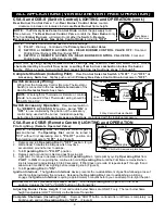

ALL APPLICATIONS (VENTED and VENT FREE OPERATION)
Pilot Location:
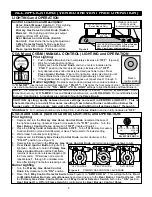
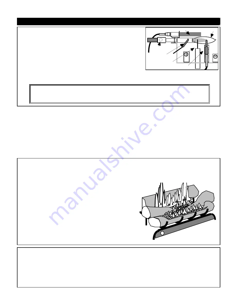
Pilot is located on right side behind front burner.
OP AMERICA Standard (Manual/Remote Models)
The Pilot flame should be steady and soft blue surrounding 1/8 inch of
the thermocouple tip as shown in Figure 7.
OP AMERICA Millivolt (Switch Model)
NOTE: The OP America Millivolt Pilot/ODS is equipped with a quick
acting thermocouple allowing gas flow to the pilot after approximately 30-
40 seconds. An additional 60 to 90 seconds time is required to fully
heat the thermogenerator and allow gas to the main burner(s).
Pilot Flame Adjustment. Pilot flame should be steady and soft
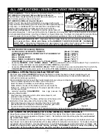
THERMOGENERATOR (Switch Models)
LP THEMOCOUPLE
NAT GAS
THERMOCOUPLE
PIEZO SPARKER
PILOT FLAME
Figure 7
AIR INTAKE
HOLES
blue extending approx. 1 inch beyond the pilot tube. If adjustment is necessary, use a narrow long stem screw driver
to turn pilot adjustment screw (see Figure 5-Switch or Figure 6-Remote). To adjust turn clockwise for less pilot flame,
counterclockwise for more pilot flame. There is no pilot adjustment available on C5-A or C5-B Manual Models.
IMPORTANT SERVICE TIP! Obstructed Pilot Air Intake Ports result in an improper gas/air mixture
and a weak pilot flame. Weak pilot flame is the NUMBER 1 SERVICE ISSUE RE NUISANCE
SHUT-OFF. Using canned compressed air , pipe cleaner or an artist's brush, clean out the opposing
Air Intake Ports located at base of Pilot (where gas supply line attaches to pilot). (Figure 7)
.
Switch Control Accessory Options:
ULTRA-SONIC WIRELESS REMOTE
(Model "F10AB)
INFRARED WIRELESS REMOTE WITH THERMOSTAT
(Model "IRRC")
WALL SWITCH
(Model "WS-1")
WALL THERMOSTAT
(Model "TS-1")
WALL TIMER (60 MINUTE TIMER)
(Model "WT-1")
CRACKLER Sound Generator option for F 1 0 A B or IRRC
(Model "CF5")
•
Accessory REMOTE LOG HOUSE (Model "RH") is available for use as a heat resistant "log" in which the
receiver portion of Wireless remote option F 1 0 A B or IRRC may be located.
•
Accessory CRACKLER LOG HOUSE (Model "CH") is available for use as a heat resistant "log" in which the
CRACKLER Sound Generator option for both the F10 AB and IRRC wireless remotes may be located.
NORMAL OPERATING CHARACTERISTICS
Each and every CHILLBUSTER that leaves the factory is quality checked to ensure compliance with our
American Gas Association certification. This check includes an operational test to ensure both satisfactory
combustion and proper operation.
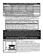
Each installation site for any vent free heater presents its own unique combustion environment. Specific factors
such as weather tightness of the home, size of the room in
which the heater is installed, central heating, ceiling fans,
drafts, altitude, the size of the firebox, paint or soot inside the
firebox, etc., all have an influence on the proper operation of any
vent free gas log set.
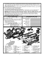
A normally operating CHILLBUSTER Gas Logs possess the
following characteristics:
•
Clean burning combustion, which, after normal break in, will
produce no soot or smoke.
•
A full bodied, lively flame. The flame will be blue at the base and a
combination of blue and yellow at the body and tips. Figure 8.
•
After initial break-in produce no odor other than the normal odors
associated with the combustion of Natural or Propane gas and/or
the environment in which the heater is operated.
Figure 8
•
Will produce water vapor (increase indoor humidity) which may be beneficial during the dry heating season.
CUSTOMER RESPONSIBILITIES AND ANNUAL MAINTENANCE
• Keep the area around the CHILLBUSTER free and clear from debris. From time to time, visually check pilot and
burner flames for proper appearance (Figures 7 and 8). Normal flame color should be yellow body surrounded
by a hard blue haze.
• The pilot, air shutters and burners must be free of lint and dirt for optimum performance. Air shutters which have
been closed or are obstructed with debris will not allow sufficient combustion air into burner. Air shutters should be
periodically cleaned of debris. Use compressed air or a soft bristle brush to clear pilot and burner(s) air intakes. Air
shutters should not be altered from factory settings. "WARNING: Failure to keep the primary air
opening(s) of the burner(s)clean may result in sooting or property damage.
10


