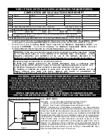
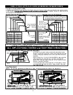
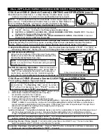

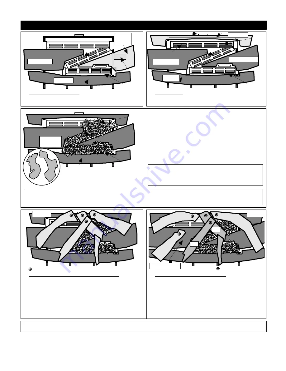
ALL APPLICATIONS (VENTED and VENT FREE OPERATION)
Front Burner
Pilot
Rear Burner
Guide
Plate
Rear Bracket
Middle Burner
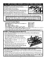
RIGHT
MIDDLE
LOG
Left Middle Log
Front Log
Front Burner
Pilot
Rear Bracket
Middle Burner
Pilot
Front Log
Left Middle Log
Right Middle Log
REAR LOG
Rear Burner
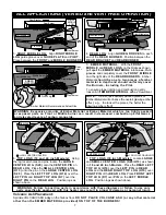
3. RIGHT MIDDLE LOG: Align RIGHT MIDDLE
LOG guide groove over GUIDE PLATE and P I L O T .
Place between the FRONT and MIDDLE BURNERS.
4. REAR LOG: Align GUIDE GROOVES to each
end of the REAR BURNER. Position between the
REAR BRACKET and REAR BURNER.
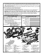
Front Burner
Pilot
Rear
Burner
Front Log
Left Middle Log
Middle Burner
Right Middle Log
Pilot
Rear Log
Ember Material Recommended Actual Size
EMBER
MATERIAL
5. EMBER MATERIAL: With the F R O N T ,
MIDDLE and REAR LOGS on the Grate as shown,
pull apart the EMBER MATERIAL into loose, thin
pieces and completely cover the FRONT, MIDDLE
and the right side of the REAR BURNERS. Ember
Material should be one to two pieces of ember
material in depth and should uniformly cover
the Burners, including the Pilot.
To ensure proper ignition and combustion gently
loosen & lift EMBER MATERIAL with a screw driver.
NOTE: Thinner, less densely packed pieces of
Ember Material will enhance the overall glowing ember
effect, e.g., the looser the pieces, the better the
glowing ember effect!
.
WARNING: Excessive amounts of Ember Material or Ember Material which is too tightly packed
or exposed ports on Front or Middle burner can result in decreased combustion performance
and elevated levels of carbon monoxide.
.
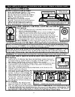
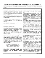
Pilot
=LOG LOCATOR HOLE/PIN
Rear Log
H14
D7
S25
H13
Pilot
=LOG LOCATOR HOLE/PIN
H15
D7
S25
H13
Rear Log
Left Middel Log
H10
D7
6. TOP LOGS (18 and 24 inch Models): Using
the log locator holes and pins, locate the LARGE
CENTER LOG (S25) onto the CENTER PIN on
REAR LOG. Place the SMALL CENTER LOG
(H13) onto the pin on the LARGE CENTER LOG
( S 2 5 ) . Place the LEFT TOP LOG (H14) over the
LEFT PIN and RIGHT TOP LOG (D7) over the
RIGHT PIN on the REAR LOG. Position logs as
shown above.
7. TOP LOGS (30 inch Models): Locate LARGE
and SMALL CENTER LOGS (S25/H13) as shown
in 18 and 24 inch Models. Place the REAR LEFT
TOP LOG (H10) over the LEFT PIN on REAR
LOG and the REAR RIGHT TOP LOG (H15) over
RIGHT PIN of the REAR LOG. Place FRONT LEFT
TOP LOG (D7) over PIN on the LEFT MIDDLE
LOG. Position logs as shown above.
WARNING: Failure to position parts in accordance with these diagrams or failure to use only
parts specifically approved with this heater may result in property damage or personal injury.
Volcanic Ash Placement:
Sprinkle VOLCANIC ASH only on the firebox floor. DO NOT PLACE VOLCANIC ASH (or any other material
other than the EMBER MATERIAL provided) ON TOP OF THE BURNERS!
7


