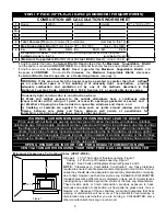
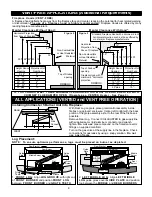
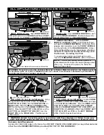
ALL APPLICATIONS (VENTED and VENT FREE OPERATION)
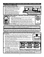
LIGHTING and OPERATION
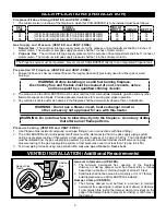
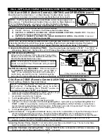
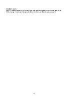
Control Locations and Description:
Valve Knob (Manual Control): Pilot Lighting,
Burner Selection (LOW, MEDIUM or HIGH).
Primary Gas Valve Control Knob (Switch
Models): Pilot Lighting and Valve gas output
adjustment from OFF to FULL.
Rear Burner Control Knob (Switch
Control): Rear Burner flame height adjustment.
3 Way Selector Switch: Mode selections:
SWITCH ON, OFF or REMOTE ACCESS ON.
Piezo Ignitor Button: Pilot Flame Ignition.
Figure 4
VALVE KNOB (Manual Model): Burner Selection
REAR BURNER CONTROL KNOB (Switch
Model): rear Burner height adjustment.
PRIMARY GAS VALVE
CONTROL KNOB
(At base of Right Rear Post)
3 WAY SELECTOR SWITCH
(Switch Models Only)
PIEZO IGNITER
BUTTON
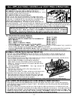
C5A-M and C5B-M (MANUAL CONTROL) LIGHTING and OPERATION
AT PILOT POSITION
SLIGHT PUSH TO
TURN OFF
FULL PUSH TO
LIGHT
OFF ON
.
.
.
OFF
ON
Valve Knob
Pilot Lighting:
1.
Push in Valve Knob and turn completely clockwise to “O F F ”. (Figure 4)
2.
Wait five minutes before lighting.
3.
Slightly push in the Valve Knob and turn counter clockwise to the
“PILOT” position (the first detent counter clockwise from "OFF".
4.
Fully depress valve knob until air is bled and gas flows to pilot. Press
Piezo Ignitor Button (Figure 3) to light pilot. Hold valve knob in until
Pilot remains lit when knob is released (approximately 30 seconds).
5.
If the appliance fails to light or if pilot goes out, repeat steps 1 through 5.
Burner Lighting:
Depress valve knob and slowly turn counter-clockwise
Piezzo
Ignitor Button
to “ON-LOW” (next detent counterclockwise from "PILOT"). This lights the front ember burner. Continue to turn
valve knob counterclockwise to the "ON - MED" or "ON - HIGH" settings to light the Middle and Rear Burners.
N O T E : The Manual Control model has four distinct burner settings: 1) PILOT: Pilot only; 2) ON-LOW: Front
Ember Burner only; 3) ON-MED: Front and Middle Ember Burners; and 4) ON-HIGH: Front and Middle Ember
Burners; Rear Burner). All positions are controlled through the Valve Knob.
CAUTION: Cycling rapidly between burner settings can result in VENTURI LIGHT-OFF. This is
characterized by a loud air flow noise resulting from internal burner combustion below the
burner ports. If this occurs, turn unit off and repeat lighting instructions steps 1 through 5.
Shutdown
: For complete shutdown (including Pilot), push Valve Knob in and turn fully clockwise to “O F F ”.
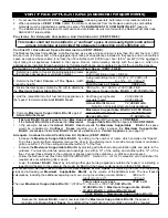
C5A-S and C5B-S (Switch Control) LIGHTING and OPERATION
Pilot Lighting:
1.
Depress and turn the Primary Gas Valve Control Knob (located at the base of
the right rear grate leg, (locate at Figure 3) clockwise to the "OFF" position. Turn the
Rear Burner Control Valve clockwise to "OFF" (locate at Figure 4).
2.
Place the 3 Way Control Selector Switch in O F F . Turn off all Remote Accessory
Controls (Switch or Hand Held Remote) or place Thermostat to it's lowest setting.
3.
Wait at least 5 minutes prior to lighting
4.
Depress and turn Primary Gas Valve Control Knob counter clockwise to the
SWITCH OFF REMOTE
ON ACCESS
ON
3 WAY CONTROL
SELECTOR SWITCH
"PILOT" position. (see Figure 5)
5.
Depress fully and hold in the Primary Gas Valve Control Knob until all air is bled and gas flows to pilot.
6.
Press Piezo Ignitor Button (Figure 3) to
light pilot. Continue to hold in Primary Gas
Valve Control Knob until the Pilot flame
remains lit when knob is released (approx 60
to 90 seconds). If Pilot does not remain lit,
repeat steps 1 . through 5 . and allow more
time after lighting Pilot before releasing knob.
Burner Lighting
:
1.
Turn the Primary Gas Valve Control
Knob fully clockwise to the "ON" position.
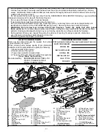
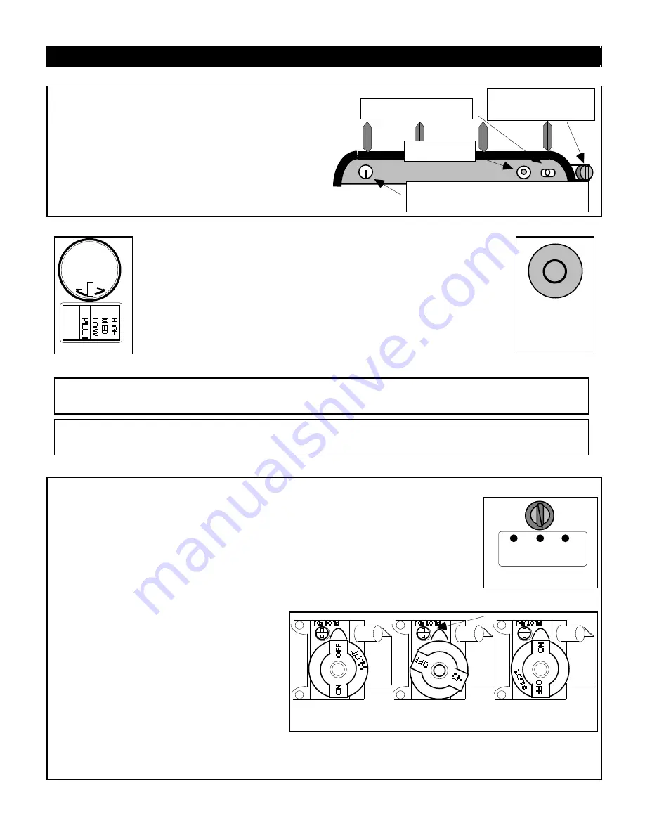
Figure 5
"OFF" POSITION
+
+
v
+
"ON" POSITION
+
+
v
+
PILOT ADJUST COVER CAP
"PILOT" POSITION
PILOT
+
v
+
+
PRIMARY GAS CONTROL VALVE KNOB
2.
Place the 3 Way Control Selector Switch (see Figure 3) to "SWITCH ON". This will light both the Front
and Middle Ember Burners simultaneously and send gas up to the Rear Burner Control Valve. With
the Primary Gas Valve Control Knob and 3 Way Control Selector Switch both in the "ON" position,
Rear Burner O n , Off and Flame Height is controlled at the Rear Burner Control Valve.
8


