


18
Log locator pins for;
C10 S25 H15
C10
D7
H15
FIGURE 44
H13
S25
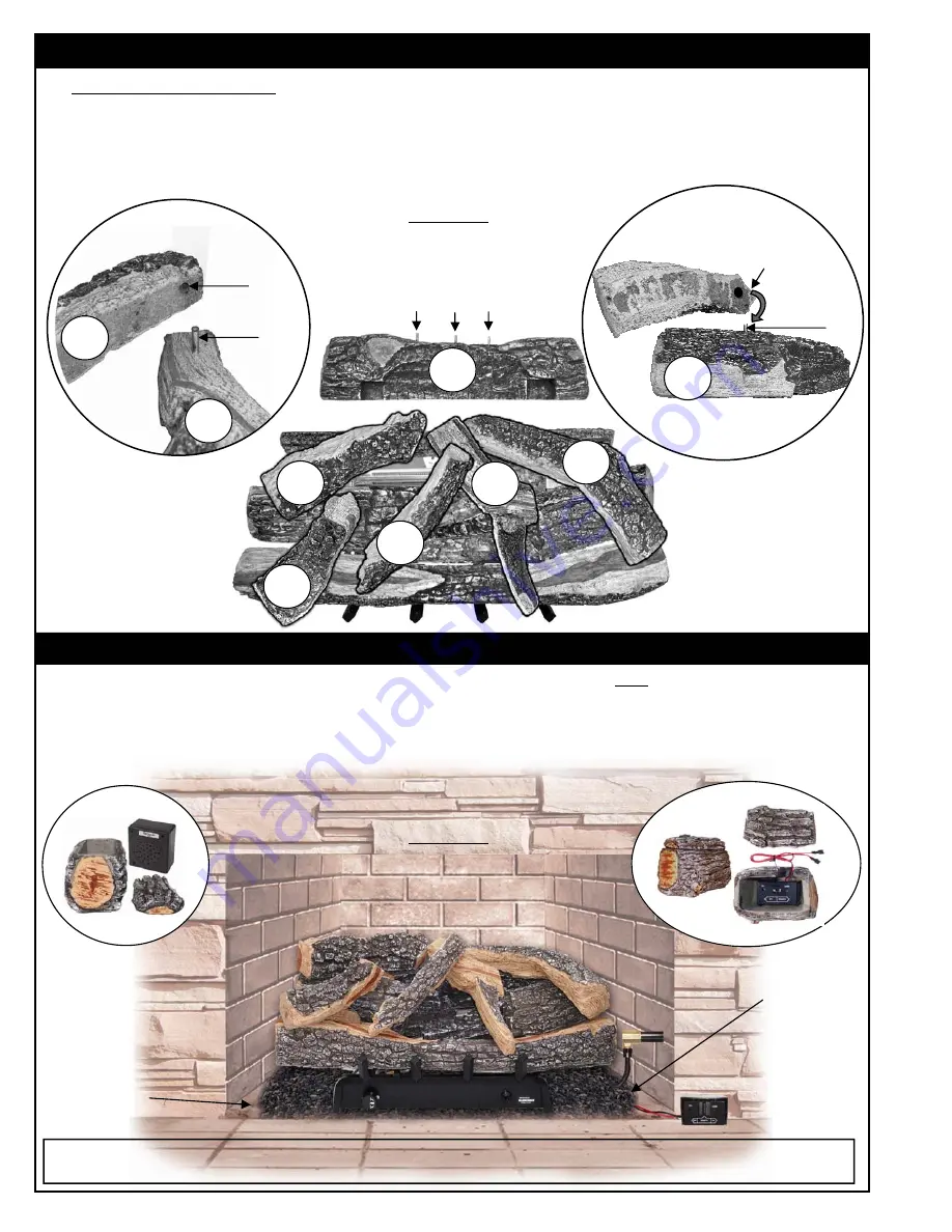
7. TOP LOGS (30 inch Models)
Align the Log locator hole on the
Large Middle Top Log (S25)
with the center
Log locator Pin on the Rear Log
(H4)
(Figures 44A and D). Next, place the
Rear Left Top Log (C10)
(Figure 44D) over the
Left Pin
on the
Rear
Log (H4)
Figure 44B) and the
Rear Right Top Log (H15)
(Figure 44A) over
Right Pin
on the
Rear Log
. Next,
place the
Front Left Top Log (D7)
(Figure 44C) over
Pin
on the
Left Middle Log
(Figures 44C and D). Position
logs as shown below in Figure 44D
D7
C)
Left Middle Log (H10)
Log Locator
Hole
STEP FOUR: HF30 TOP LOG AND RECEIVER PLACEMENT
REMOTE RECEIVER PLACEMENT
B)
H4
H10
A) Remote Receiver for
“RE” and “SE”
Models
Black Volcanic Ash
used to help conceal
flex connector
and wiring
S25
H13
Log Locator
Hole
Log Locator
Pin
A)
D)
Black Volcanic
Ash used as
Floor dressing.
The Remote Receiver (-RE and -SE models) can be adversely affected by heat and must be placed as
far forward and
to the side of your CHILBUSTER™ as possible
(Figure 45A). When connecting receiver to Motordrive (“-RE” models)
or Solenoid (“SE models) be sure to match red and black connectors, red to red and black to black). Our optional
Ceramic Log House
accessory (RH2) (Figure 45B), offers heat protection for the Remote Receiver while being pleasing
to the eye. Also sold separately, is our “Stand Alone Crackler” (CH) which mimics the sound of a crackling fire adding a
cozy feel to your log set.
Log Locator
Pin
FIGURE 45
WARNING:
Failure to position the parts in accordance with these diagrams or failure to use only parts specifically
approved with this heater may result in property damage or personal injury.
C)
B)


