


20
VENTED MODELS IMPORTANT!
CHIMNEY DAMPER MUST BE WIDE OPEN! THE FLUE MUST VENT ALL PRODUCTS OF COMBUSTION.
DAMPER AND GLASS DOORS MUST BE FULLY OPEN BEFORE LIGHTING OR BURNING FOR PROPER
VENTILATION AND TO PREVENT HEAT DAMAGE TO VALVE.
NOTE:
The “
EASY” Safety Valve
has complete control of gas to the pilot and burners. It
cannot be turned to
“OFF”
without first depressing knob to the
“PILOT”
position and then rotating clockwise to
“OFF”.
During the heating season
leave valve knob in
“PILOT”
position for convenience. Otherwise, turn to
“OFF”
position for any prolonged non-use.
PILOT FLAME ADJUSTMENT:
If adjustment is necessary, use a narrow long stem screw driver to turn pilot adjustment
screw. To adjust turn clockwise for less pilot flame, counterclockwise for more pilot flame.
IMPORTANT SERVICE TIP!
Obstructed Pilot Air Intake Ports result in an improper gas/air mixture and a weak pilot
flame.
Weak pilot flame is the NUMBER 1 SERVICE ISSUE REGARDING NUISANCE SHUT-OFF.
Using canned
compressed air, a pipe cleaner or an artist's brush, clean out the opposing air intake ports located at the base of the
pilot (where the gas supply line attaches to the pilot) (See page 19, Figures 49A and B).
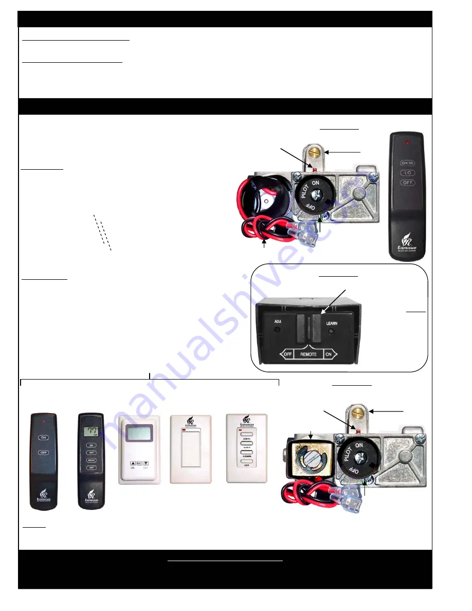
STEP TWO: PILOT ADJUSTMENT (ALL MODELS)
STEP THREE: BURNER OPERATION (“RE” VARIABLE FLAME HEIGHT AND“SE” REMOTE READY MODELS)
1. Turn
Valve Knob
to
“ON”
position (Figure 50A)
2. Slide switch on the
Receiver
(Figure 51) to
“REMOTE”
position.
“RE Models
3. Depress the
“ON/HI”
button on the
TRANSMITTER
(Figure 50B) until a click is heard. The burner will then
light to “Full on”
NOTE:
Reducing the burner flame can be achieved by pressing
the “
LO”
button one beep at a time to the desired flame height.
Pressing the
“ON/HI”
button one beep at a time will raise the
burner flame). To verify the burner is completely off, press the
“OFF”
button once.
Variable flame height can only be
achieved via the hand held remote.
On/Off Solenoid
Wireless On/Off
Remote with
Wireless Wall
Thermostat
(TS-2R)
“SE” Models
3. Consult Operating Instructions for Accessory Control (below).
4. Adjust the burner flame height by turning the
Valve Knob
(Figure 52A) clockwise to lower and counter-clockwise to raise
up to full on.
NOTE:
During the heating season leave Valve Knob in
“PILOT”
position for convenience. Otherwise, turn to
“OFF”
position
for any prolonged non-use.
FIGURE 50
DC Variable Motordrive
B) Transmitter
Accessory Controls
C) Pilot Adjustment
Screw
Knob Position
Indicator
A) Valve Knob
Wireless Wall Timer
(30/60/120 Minutes)
Wireless On/Off
Remote
(SR-2R)
Wireless Wall
Switch
C) Pilot Adjustment
Screw
Knob Position
Indicator
A) Valve Knob
FIGURE 51
Slide Switch in “REMOTE” Position
FIGURE 52
NOTE:
THE RECEIVER HAS
3 POSITIONS;
“OFF”, “FULL ON”
AND “REMOTE
ACCESS ON”


