background image

22 


Blue 

Blue and Yellow 

NORMAL OPERATING CHARACTERISTICS 


Each and every 

CHILLBUSTER™ 

that leaves the factory is quality checked to ensure compliance with our


certification. 

This check includes an operational test to ensure both satisfactory combustion and proper operation. 

Each installation site for any vent free heater presents its own unique combustion environment. Specific factors such as 

weather tightness of the home, size of the room in which the heater is installed, central heating, ceiling fans, drafts,  

altitude, the size of the firebox, paint or soot inside the firebox, etc., all have an influence on the proper operation of any 

vent free gas heater. 


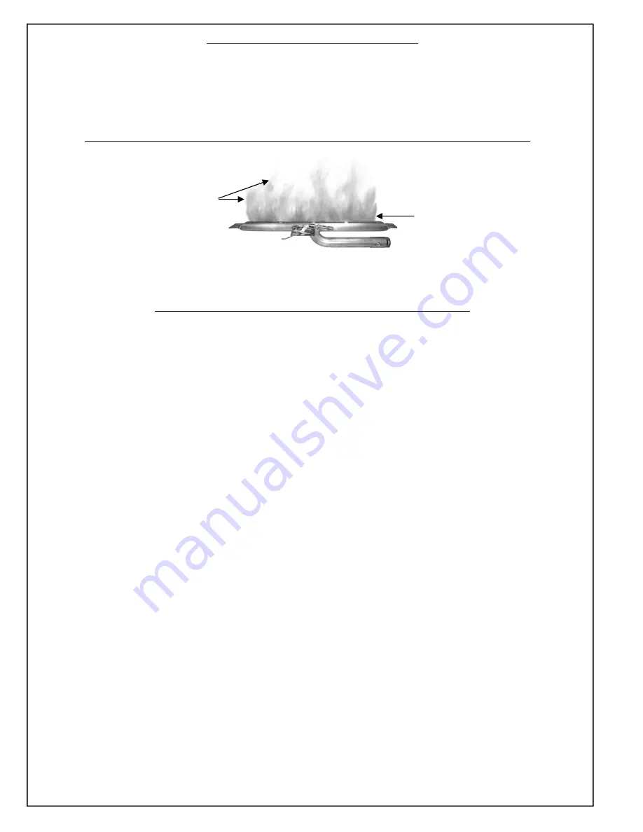
A  normally operating CHILLBUSTER™ Gas Fire Set possess the following characteristics: 


• 

Clean burning combustion, which, after normal break in, will produce no soot or smoke.


• 

A full bodied, lively flame. The flame will be blue at the base and a combination of blue and yellow at the body and tips. 


• 

After initial break-in produce no odor other than the normal odors associated with the combustion of Natural or Propane 

gas and/or the environment in which the heater is operated.  

• 

Will produce water vapor (increase indoor humidity) which may be beneficial during the dry heating season. 


CUSTOMER RESPONSIBILITIES AND PERIODIC MAINTENANCE 


• 

Keep the area around the 

CHILLBUSTER™ 

free and clear from debris. From time to time, visually check pilot and 

burner flames for proper appearance (see section above for burner; see Page 20 Fig. 34 for Pilot). 

• 

Periodically examine and clean the venting system. Once every year, a qualified agency or certified chimney sweep 
should examine and clean the venting system of the solid fuel burning fireplace in which the  

CHILLBUSTER™ 


installed (if applicable). 

• 

The air shutter and burner must be free of lint and dirt for optimum performance. Air shutters which have been closed or 
are obstructed with debris will not allow sufficient combustion air into the burner.  Air shutters and burner ports (where 
flame comes out of the burner) should be periodically cleaned of debris.  Use compressed air and/or a soft bristle brush 
to clean burner ports and air shutter area. 

Air  shutters should not be altered from factory settings

.  


WARNING: Failure to keep the burner primary air opening clean may result in sooting or property damage. 


• 

Keep air intake holes of ODS Pilot (see Page 20 Figure 34) clear of lint.  Over time lint will accumulate in these holes, 
and will eventually result in nuisance pilot outage or difficulty in lighting pilot.  Clean these holes annually with  
compressed air or a pipe cleaner.  

NOTE: Lint and dust in the Air Intake Holes is the #1 cause of nuisance pilot 

outage.


• 

Do not operate in a dirty firebox or in a previously used firebox which has not had all soot completely removed or chim-
ney flue cleaned. Previously used fireboxes must have flue and stack professionally cleaned by a chimney sweep.   

   Additionally, firebox walls and damper must also be thoroughly cleaned of all burn residue and soot using a damp cloth,      
   sponge or brush. 

• 

Do not operate this set with any burner objects other than the 

RASMUSSEN 

FireBalls, FireShapes or FireStones  

   specifically designed and approved for use with this Burner System. 

• 

Do not use with blower inserts or heat exchangers. 

• 

If used, glass doors must be wide open when burner is on. 

• 

Do not remove Rating Plate/Warning Tags. These tags serve you and any future user as an integral safety and    

   identification component of the 

CHILLBUSTER™ 

gas log heater. 

Removing these tags voids the warranty.


• 

WARNING: 


Do not allow fans to blow directly into fireplace.  Avoid any drafts that alter burner flame patterns.


   Do not place blower inside area of firebox. Ceiling fans may create drafts that alter burner flame patterns. Sooting and  
   improper burning may occur. Sooting can settle on surfaces outside the fireplace. 

• 

During periods of heavy use, inspect frequently for evidence of sooting. If sooting is present, discontinue use until source 
of sooting is determined and corrected. 

• 

Maintain positioning of FireBalls, FireShapes or FireStones (Pages 9 thru 18)


at all times.  

• 

Occasionally, you may use a soft bristle brush or damp cloth to clean objects. 


Summary of Contents for CHILLBUSTER 5

Page 1: ...performed by a qualified installer service agency or the gas supplier WARNING If the information in this manual is not followed exactly a fire or explosion may result caus ing property damage personal injury or loss of life This appliance may be installed in an aftermarket permanently located manufactured mobile home where not prohibited by local codes This appliance is only for use with type of g...

Page 2: ...ted before use and at least annually by a professional service person More frequent cleaning may be required due to excessive lint from carpeting bedding material etc It is imperative that control compartments burners and circulating air passageways of the appliance be kept clean WARNING Any change to this heater or its controls can be dangerous This appliance is intended for supplemental heating ...

Page 3: ...TV KE2 20 3 8 x 1 2 FIP Flared Brass Fitting A1 21 Damper Clamp DC1 22 Flex Connector SSCB 18 23a Rating Serial Plate 23b Warning Plate 24 Variable Flame Height Motordrive RE Models STV VMD 25 Remote Ready Solenoid SE Models STV LS See following page for wireless accessories 26 Grate C5 OLD STYLE C5E 27 Heat Shield misc part 28 Pilot Assembly Natural Gas ODS OP N 29 Plot Assembly Propane ODS OP P ...

Page 4: ...ld ON OFF Remote SR 2R b Wireless Hand Held ON OFF Remote with Thermostat THR 2R c Wireless Wall Timer 30 60 120 Minutes WT 2R d Wireless Wall Thermostat TS 2R e Wireless Wall Switch WS 2R 51 Wireless Hand Held Variable Remote for RE Models STR RMD 52 Remote Receiver for SE or RE models BPR3 41 HF30 Right Middle Log H12 42 Left Top Log for 18 and 24 Models H14 43 Middle Top Log all models S25 44 2...

Page 5: ...crease the Actual Btu Hr used by the same amount You may also choose to operate your ALTERNA as a Vented Appliance instead See notes and warnings regarding vented installation on Page 7 Adequate Combustion And Ventilation Air Options Increasing the Maximum Supportable Btu Hr 1 Add to the number of rooms which comprise the Space To do this you must either completely remove the door to an adjoining ...

Page 6: ...r plumbing electrical and gas lines and at other openings VENT FREE APPLICATIONS COMBUSTION AIR CALCULATIONS COMBUSTION AIR CALCULATIONS WORKSHEET 1 Room Width Length Height W x L x H Vol ft 1a 1a 1b 1b 1c 1c 1d 1d 2 Total Volume ft The Sum of Volume of all rooms add lines 1a thru 1d 2 3 Max Supportable Btu Hr Total Volume ft 50 x 1000 divide line 2 by 50 then multiply by1000 3 4 4a Btu hr 4b Btu ...

Page 7: ...fire In most cases they should also be adequate to prevent any discoloration or warping due to heat However each and every decorative gas appliance installation CHILLBUSTER included presents a different and com pletely unique set of circumstances involving many variables beyond the control of the manufacturer These include paint or finish composition previous exposure to heat methods and quality o...

Page 8: ... provisions for combustion and ventilation air must conform with The National Fuel Gas Code ANSI Z223 1 NFPA54 or The CSA B149 1 Natural Gas and Propane Installation Code latest edition STEP ONE PREPARATION ALL MODELS 1 Verify that the Valve Assembly is correctly matched to the set burner and gas supply 2 Insure that Fireplace Gas Supply is off Figure 1A 3 Thoroughly clean fireplace floor of any a...

Page 9: ...Width Minimum 6 greater than log set size FIGURE 3 Long Valve Key K2 sold separately Rear Width Not less than log set size Log Locator Pins Guide Groove Guide Groove C 1 2 FIP x 3 8 Flared Elbow B Valve Input FIGURE 5 FIGURE 4 Log Locator Pins C Rear Log MINIMUM AND MAXIMUM INLET GAS SUPPLY PRESSURE The minimum inlet gas supply pressure shall be 5 inches of water column on Natural Gas and 11 inche...

Page 10: ...oove Figure 6A with right end of Front Burner Figure 6 and 7B and position Front Log between Front Burner and Grate Teeth as shown in Figure 7C A Left Middle Log Guide Groove B Left guide Plate B Front Log Guide Groove Grate Teeth C Front Log Left Guide Plate B Right End of Front Burner Rear Bracket Front Burner Left Middle Log Left Guide Plate Rear Burner Middle Burner Right Guide Plate RightMidd...

Page 11: ...r can result in decreased combustion performance and elevated levels of carbon monoxide STEP FOUR HF18 LOG PLACEMENT AND PAN MEDIUM Volcanic Ash Placement Volcainc Ash should only be used on the firebox floor as floor dressing Figure 14A above DO NOT place Volcanic Ash or any other material other than the Ember Material provided on top of the burners FIGURE 12 FIGURE 13 FIGURE 15 Rear Bracket Rear...

Page 12: ...e Receiver RE and SE models can be adversely affected by heat and must be placed as far forward and to the side of your CHILLBUSTER as possible Figure 19A When connecting receiver to Motordrive RE mod els or Solenoid SE models be sure to match red and black connectors red to red and black to black Our optional Ceramic Log House accessory Figure 19B offers heat protection for the Remote Receiver wh...

Page 13: ... position log between the Middle Burner and Rear Burner as shown in Figure 23 3 RIGHT MIDDLE LOG Align Right Middle Log Figure 24A guide groove over Right Guide Plate Figure 24B and Pilot Figure 24C Place between the Front Burner and the Middle Burner Figure 25A Rear Bracket Front Burner B Front Log Guide Groove Grate Teeth C Front Log Left Guide Plate FIGURE 21 1 FRONT LOG Align Front Log Guide G...

Page 14: ... on the firebox floor as floor dressing Figure 28A above DO NOT place Volcanic Ash or any other material other than the Ember Material provided on top of the burners Rear Burner Rear Bracket FIGURE 27 FIGURE 28 FIGURE 29 Rear Burner Guide Groove A PAN MEDIUM 5 EMBER MAGIC With the Front Middle and Rear Logs on the Grate as shown in Figure 28 bottom left pull the Ember Magic apart into loose thin p...

Page 15: ...E 30 The Remote Receiver RE and SE models can be adversely affected by heat and must be placed as far forward and to the side of your CHILLBUSTER as possible Figure 33A When connecting receiver to Motordrive RE mod els or Solenoid SE models be sure to match red and black connectors red to red and black to black Our optional Ceramic Log House accessory Figure 33B offers heat protection for the Remo...

Page 16: ... Burner Front Burner B Right Guide 3 RIGHT MIDDLE LOG Align Right Middle Log Figure 38A guide groove over Right Guide Plate Figure 38B and Pilot Figure 38C Place between the Front Burner and the Middle Burner Figure 39A Ends of Front Burner B Front Log Guide Grooves FIGURE 34 FIGURE 35 1 FRONT LOG Align Front Log Guide Grooves Figure 34A with ends of Front Burner Figure 34 and 35B and position Fro...

Page 17: ...ar Burner Guide Groove A PAN MEDIUM 5 EMBER MAGIC With the Front Middle and Rear Logs on the Grate as shown in Figure 28 bottom left pull the Ember Magic apart into loose thin pieces and completely cover the Front Middle and the right side of the Rear Burners Ember Material should be one to two pieces of ember material in depth and should uniformly cover the Burners Including the Pilot To ensure p...

Page 18: ...o help conceal flex connector and wiring S25 H13 Log Locator Hole Log Locator Pin A D Black Volcanic Ash used as Floor dressing The Remote Receiver RE and SE models can be adversely affected by heat and must be placed as far forward and to the side of your CHILBUSTER as possible Figure 45A When connecting receiver to Motordrive RE models or Solenoid SE models be sure to match red and black connect...

Page 19: ... least five minutes to allow gas which may have accumulated around burner to escape then slightly push in the EASY Safety Valve Knob and turn to PILOT OFF Figure 47 3 Depress knob until air dissipates and gas flows to pilot located on the right side behind the front burner Press the Piezo Ignitor Button to light the pilot Figure 48A and continue to hold knob in until pilot remains lighted after kn...

Page 20: ...ATION RE VARIABLE FLAME HEIGHT AND SE REMOTE READY MODELS 1 Turn Valve Knob to ON position Figure 50A 2 Slide switch on the Receiver Figure 51 to REMOTE position RE Models 3 Depress the ON HI button on the TRANSMITTER Figure 50B until a click is heard The burner will then light to Full on NOTE Reducing the burner flame can be achieved by pressing the LO button one beep at a time to the desired fla...

Page 21: ... operating the heater This appliance is equipped with a Safety Pilot System designed to shut itself off if enough fresh air is not available Additional ventilation may be optained by opening a window or a door to another room Although your CHILBUSTER is very realistic in appearance it is not a real wood burning fireplace Matches paper garbage or any other foreign material MUST NOT be thrown on top...

Page 22: ...e flame comes out of the burner should be periodically cleaned of debris Use compressed air and or a soft bristle brush to clean burner ports and air shutter area Air shutters should not be altered from factory settings WARNING Failure to keep the burner primary air opening clean may result in sooting or property damage Keep air intake holes of ODS Pilot see Page 20 Figure 34 clear of lint Over ti...

Page 23: ...r Relieve any tight bends or kinks in the Flex Connector Switch to a smooth aluminum connector which can be purchased at hardware or home improvement stores Burner Flame is Too High 8 12 Above Top Logs or Too Low Below Top Logs Incorrect gas supply pressure or burner orifice used 1 Ensure gas type of set is proper for gas type being used Make sure the gas pressure coming into the fireplace falls b...

Page 24: ...of incidental or consequential damages so the above limitation or exclusion may not apply to you 3 The maximum liability of RASMUSSEN in connection with this limited warranty shall not in any case exceed the contract price paid for the product claimed to be defective or unsuitable 4 This warranty does not extend to any product manufactured by RASMUSSEN which has been subjected to misuse neglect ac...

Reviews: