


9
STEP TWO: BURNER INSTALLATION AND GAS SUPPLY CONNECTION
1. Insure that the Gas Supply to the Fireplace is turned off and verify correct gas type and proper gas pressures.
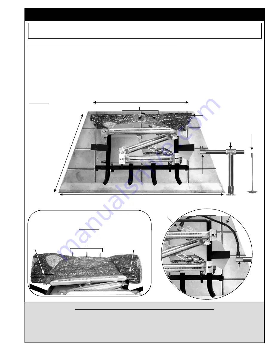
2. Thread
1/2” FIP x 3/8” Flared Elbow
(Figure 3A) onto the
Gas Supply Pipe
(Figure 3B) and wrench tighten.
3. Place
Rear Log
on grate with flat unpainted side facing rear wall and
Guide Pins
facing up (Figures 3C and 4
below). The left and right
Log guide
grooves
should lock in place behind the left and right ends of the rear burner.
4. Place Chillbuster™ inside firebox or approved enclosure centered from left to right and as far to the rear of the
firebox as possible. Remove rear log and thread one end of the supplied
Flex Connector
(Figure 5A bottom right)
to the
Valve Input
(Figure 5B), then connect the other end to the
1/2” FIP x 3/8” Flared Elbow (Figure 5C)
attached to the Gas Supply Pipe. If Flex Connector is bent into too small a radius it may kink or break causing air
flow noise and /or gas leaks.
INSTALLATION AND CONNECTION
(Vent Free Models consult “Step One, Preparation” on previous page before continuing)
Depth
Minimum
14”
B) Gas Supply Pipe
A) 1/2” FIP x 3/8”
Flared Elbow
Front Width (Minimum 6” greater than log set size)
FIGURE 3
Long Valve Key (K2)
(sold separately)
Rear Width (Not less than log set size)
Log Locator Pins
Guide Groove
Guide Groove
C) 1/2” FIP x 3/8”
Flared Elbow
B) Valve Input
FIGURE 5
FIGURE 4
Log Locator Pins
C) Rear Log
MINIMUM AND MAXIMUM INLET GAS SUPPLY PRESSURE
The minimum inlet gas supply pressure shall be 5 inches of water column on Natural Gas and 11 inches of water
column on Propane. The maximum inlet gas supply pressure shall be 7 inches of water column on Natural Gas
and 14 inches of water column on Propane. The appliance and its main gas valve must be disconnected from the
gas supply piping system during any pressure testing of that system at test pressures in excess of 1/2 psi (3.5
kPa) and isolated from the gas supply piping system during any pressure testing at equal to or less than 1/2 psi
(3.5 kPa).
A) Flex Connector
Connected from
1/2” FIP x 3/8”
Elbow to
Valve
WARNING:
Failure to position the parts in accordance with these diagrams or failure to use only parts specifically
approved with this heater may result in property damage or personal injury.
The minimum size of the fireplace in which this CHILLBUSTER™ is to be installed is as follows; Minimum opening height 17 in.
(previous page), Firebox depth, 14 inches (Figure 3 above). Front width shall be a minimum of 6” greater than log set size.


