background image


5

Adequate Combustion And Ventilation Air Options: 

• Increase 

the 

Maximum Supportable Btu/Hr 

by adding to the number of rooms which comprise the "Space". 

To do this you must ether completely remove the door to an adjoining room or provide two permanent ventilation 
grills; one within 12" of the ceiling and another within 12" of the floor. 

• Increase 

the 

Maximum Supportable Btu/Hr 

by providing extra fresh air using ventilation grills and ducts to the 

outdoors. You must provide two permanent openings, one within 12" of the ceiling and another within 12" of the 
floor. Connect these directly to the outdoors or spaces open to the outdoors, e.g., attics or crawl spaces.  

• Follow 

the 

National Fuel Gas Code NFPA 54/ANSI Z223.1, Section 5.3, Air for Combustion and Ventilation

 for 

required size of ventilation grills or ducts. 

• Lower 

the 

Actual Btu/Hr Used 

by relocating other gas burning appliances outside the "space" or installing a  

lower Btu/Hr heater. In the example, the maximum Btu/Hr of the heater could be no more than 28,160 Btu/Hr.


For our example, we have chosen to add to our 

Total Volume of the Space 

by removing the door to an adjoining 

study and increasing our 

Maximum Supportable Btu/Hr 

by the volume of the additional room. The new "space" 

calculations, including the additional adjoining room are:

 Living room/dining room & Kitchen 

3008 cu ft 


Study (9' x 10' x  8') 


  720 cu ft 


Total volume of space  

3728 cu ft 

The new Maximum Supportable Btu/Hr  = (3728 cu ft  ÷ 50 cu ft ) x 1000 = 74,560 Btu/Hr 
       74,560 

Btu/Hr 

Maximum 

Supportable 

Btu/Hr 


             - 

72,000 Btu/Hr = Actual Btu/Hr Used 


2,560 

Btu/Hr 

Remaining 

Supportable 

Btu/Hr 


Because the 

Actual Btu/Hr 

used is now less than the 

Maximum Supportable Btu/Hr

, the space is  

considered an 

Unconfined Space

. No additional fresh combustion and ventilation air would be required. 
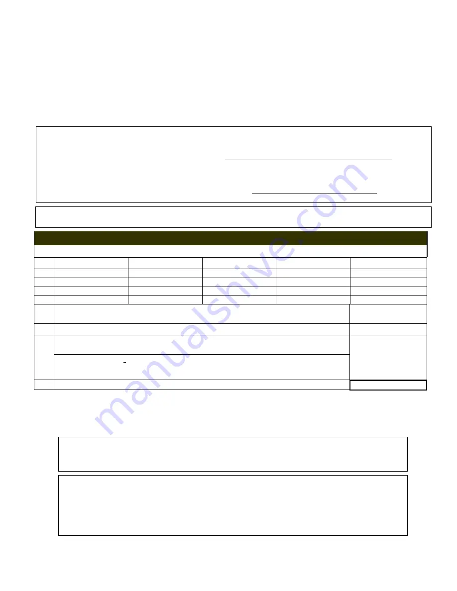
 

VENT FREE OPERATION


COMBUSTION AIR CALCULATIONS WORKSHEET


1. 

Room Width  Length Height W 

x

 H=Vol. (ft3) 

1a. 


1b. 


1c. 


1d. 


2.  Total Volume (ft3)

sum of Volume (ft3) of all rooms                         (sum lines 1a. thru 

1d.) 

2.


3.  Max Supportable BTu/Hr

=Total Volume (ft3) ÷ 50 x 1000                (line 2 ÷ 50 x1000) 

3.


4.  4a.


3


Btu/hr 

4b.

3


Btu/hr 

4c.


3


Btu/hr 

4d.


3


Btu/hr 


  Actual Btu/hr used

 = Sum Btu/hr of all fuel burning appliances inside the space              

identified as rooms 1a. thru 1.b                                                                               (sum 
line 4a thru 4d.) 

 
4.


5.  (Maximum Supportable BTu/Hr) 

minus

 (Actual BTu/hr Used)

    (Line 3 - line 4) 

5.                          *


* If 

Line 

5

 is greater than zero, the 

Actual BTu/Hr Used 

is 

less

 than the 

Maximum Supportable BTu/Hr

 and 

the space is considered 

UNCONFINED

.


No additional fresh combustion and ventilation is required. 

* If 

Line 

5

 is zero or less, the 

Actual BTu/Hr Used 

is 

greater

 than 

Maximum Supportable BTu/Hr 

and the 

space is 

CONFINED. 

You must either 

increase 

the

 Maximum Supportable BTu/Hr, decrease

 the 

Actual 

BTu/Hr Used

 or 

operate as a Vented Appliance 

(see page 4). 


WARNING: If the area in which the heater may be operated is smaller than that defined as an 
unconfined space or if the building is of unusually tight construction, provide adequate 
combustion and ventilation air by one of the methods described in the National Fuel Gas Code, 
ANSI Z223.1, 1992, Section 5.3 or applicable local codes. 


Unusually tight construction is construction where: 
a) Walls and ceilings exposed to the outside atmosphere have a continuous water vapor retarder 
with a rating of 1 perm or less with openings gasketed or sealed, and  
b) Weather stripping has been added on openable windows and doors, and  
c) Caulking or sealants are applied to areas such as joints around window and door frames, 
between sole plates and floors, between wall panels, at penetrations for plumbing, electrical, and 
gas lines, and at other openings. 


Summary of Contents for Chillbuster CL-11-C9A-ME

Page 1: ...use any phone in your building Immediately call your gas supplier from a neighbor s phone Follow the gas supplier s instructions If you cannot reach your gas supplier call the fire department Installation and service must be performed by a qualified installer service agency or the gas supplier WARNING If the information in this manual is not followed exactly a fire or explosion may result caus ing...

Page 2: ...s very realistic in appearance it is not a real wood burning fireplace Matches paper garbage or any other material must not be thrown on top of the logs or into the flames Avoid contact with the logs grate or any other part which may be hot Always ensure that the fireplace screen is closed when the appliance is operating ALL APPLICATIONS IMPORTANT INSTALLATION INFORMATION WARNING Design certified ...

Page 3: ...djustment shall be 5 inches of water column The maximum inlet gas supply pressure shall be 7 inches of water column 2 Propane Gas The minimum inlet gas supply pressure for the purpose of input adjustment shall be 11 inches of water column The maximum inlet gas supply pressure shall be 14 inches of water column The Propane source must be regulated Never connect CHILLBUSTER directly to an unregulate...

Page 4: ...The National Fuel Gas Code defines a confined space as a space whose volume is less than 50 cubic feet per 1 000 Btu per hour 4 8m3 per kW of the aggregate input rating of all appliances installed in that space and an unconfined space as a space whose volume is not less than 50 cubic feet per 1 000 Btu per hour 4 8m3 per kW of the aggregate input rating of all appliances installed in that space Ro...

Page 5: ...red an Unconfined Space No additional fresh combustion and ventilation air would be required VENT FREE OPERATION COMBUSTION AIR CALCULATIONS WORKSHEET 1 Room Width Length Height W x L x H Vol ft3 1a 1b 1c 1d 2 Total Volume ft3 sum of Volume ft3 of all rooms sum lines 1a thru 1d 2 3 Max Supportable BTu Hr Total Volume ft3 50 x 1000 line 2 50 x1000 3 4 4a 3 Btu hr 4b 3 Btu hr 4c 3 Btu hr 4d 3 Btu hr...

Page 6: ... from top of fireplace opening Mantel See Charts and Diagrams shown at Figures 1 and 2 NOTE Clearances to Combustible Construction are those distances required to ensure that a fireplace mantel or facing will not catch fire In most cases they should also be adequate to prevent any discoloration or warping due to heat However each and every Gas Log Installation CHILLBUSTER included presents a diffe...

Page 7: ...F YOU CANNOT MEET THESE MINIMUM CLEARANCES YOU MUST OPERATE HEATER WITH CHIMNEY FLUE DAMPER OPEN Operate as a VENTED Heater See Page Three ALL APPLICATIONS VENTED and VENT FREE OPERATION ASSEMBLY AND INSTALLATION WARNING Failure to position the parts in accordance with these diagrams or failure to use only parts specifically approved with this heater may result in property damage or personal injur...

Page 8: ...and REAR BOTTOM COALS Place BOTTOM COALS C9A 4 coal array C9B 5 coal array into Stainless Steel Lifters and center 2 TOP COALS Place TOP COALS C9A 3 coal array C9B 4 coal array on top and between BOTTOM COALS and center Volcanic Ash Placement Place VOLCANIC ASH only on the firebox floor DO NOT PLACE VOLCANIC ASH or any other material ON TOP OF BURNER ...

Page 9: ...t Continue to hold in Primary Gas Valve Control Knob until the Pilot flame remains lit when knob is released approx 60 to 90 seconds If Pilot does not remain lit repeat steps 1 through 5 and allow additional time after Figure 7 ON POSITION v PILOT v PILOT ADJUST COVER CAP lighting Pilot before releasing knob Switch Control Manual ON OFF After successful pilot lighting allow 60 90 seconds for the T...

Page 10: ...ceiver switch to OFF C9 R Remote Control LIGHTING and OPERATION Pilot Lighting Remote Operated Valve NOTE The Operating Dial has complete control of gas to pilot and burner The Operating Dial cannot be turned to OFF without first depressing dial in PILOT position and then rotating clockwise to OFF see Figure 8 1 Depress and turn Operating Dial to OFF position Fig 8 2 Wait at least 5 minutes to all...

Page 11: ...E RE NUISANCE SHUT OFF Using canned compressed air pipe cleaner or an artist s brush clean out the opposing Air Intake Ports located at base of Pilot where gas supply line attaches to pilot Figure 9 ALL APPLICATIONS VENTED and VENT FREE OPERATION NORMAL OPERATING CHARACTERISTICS Each and every CHILLBUSTER that leaves the factory is quality checked to ensure compliance with our American Gas Associa...

Page 12: ... also be thoroughly cleaned of all burn residue and soot using a damp cloth sponge or brush Do not operate this set with any logs other than the RASMUSSEN CHILLBUSTER Refractory Logs specifically designed and approved for use with this Burner System Do not use with blower inserts or heat exchangers If used glass doors must be wide open when burner is on Do not remove Rating Plate Warning Tags Thes...

Page 13: ...C9B 6 1 4 Front Burner Gas 12 Heat Shield 30 Remote Valve 2 Bottom Coal Array 2 Supply Connector 13 Grate 31 Remote Receiver 4 coal C9a 5 coal C9B 7 Rear Burner 32 Remote transmitter 3 3 8 Gas Supply 8 Front Burner C9 S Switch Connector 9 ODS Pilot N or LP 20 MV Valve 5 0 or 10 0 4 1 4 Rear Burner Gas MV or Standard 21 3 Way Switch S Model Supply Connector 10 Rear Burner Orifice Holder 22 Piezo ...

Page 14: ...ARRANTY The following warranty has been drafted to comply with the MAGNUSON MOSS WARRANTY ACT applicable to products manufactured after July 4 1975 It replaces and supersedes any warranty in this package or in any printed literature ...

Page 15: ...idental or consequential damages of any kind whether based upon warranty contract or negligence arising in connection with the sale use or repair of the product Some states do not allow the exclusion or limitation of incidental or consequential damages so the above limitation or exclusion may not apply to you 3 The maximum liability of RASMUSSEN in connection with this limited warranty shall not i...

Reviews: