background image


9


ALL APPLICATIONS (VENTED and VENT FREE OPERATION)


LIGHTING and OPERATION 


Control Locations and Description


All Models (C9-S-R) 
• 

Primary Gas Valve Control Knob (Switch 
Models):

  Pilot Lighting and Valve gas output 

adjustment from OFF to FULL. 

See Figure 7


• 

Switch Models (C9-S) 3 Way Selector Switch:


Mode selections: SWITCH ON, OFF REMOTE 
ACCESS ON.  

See Figure 6. 

• 

Switch Models (C9-S) Piezo Ignitor Button:  

Pilot Flame Ignition.
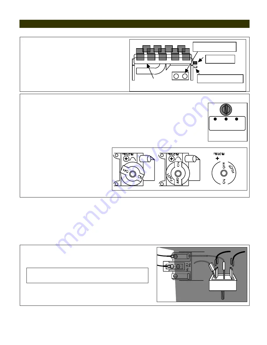


Figure 4

3 WAY SELECTOR SWITCH 

(Switch Models Only)

PIEZO IGNITER  

BUTTON

Pilot Position

PRIMARY GAS VALVE 

CONTROL KNOB 


C9-S (Switch Control) LIGHTING and OPERATION


Pilot Lighting:


1.  Depress and turn the 

Primary Gas Valve Control Knob 

(located at the base of the   right 

rear grate leg,  clockwise to the 

"OFF" 

position.  

See Figures 4 and 7.


2. Place the 

3 Way


Control Selector Switch 

in 

OFF (Fig 6)

.  Turn off all Remote 


Accessory Controls (Switch or Hand Held Remote) or place Thermostat to lowest setting. 

3.  Wait at least 5 minutes prior to lighting 
4.  Depress and turn 

Primary Gas Valve Control Knob

 counter clockwise to the


"PILOT"

 position. (

Figure 7

)


SWITCH  OFF  REMOTE 
    ON                ACCESS 
                              ON

3 WAY CONTROL  

SELECTOR SWITCH

Figure 6

5.  Depress fully and hold in the 

Primary 


Gas Valve Control Knob

 until all air is 


bled and gas flows to pilot. 

6. Press 

Piezo Ignitor Button


(Figure 3) to light pilot.  Continue to hold 

 in 

Primary Gas Valve Control


Knob


until the Pilot flame remains lit when knob 


is released (approx 60 to 90 seconds).  If 


Pilot does not remain lit, repeat steps 

1.


 through 

5.

 and allow additional time after  

Figure 7

"ON" POSITION

+

+

   v

+

+

PILOT

+

   v

+

+

PILOT ADJUST  COVER CAP

lighting Pilot before releasing knob.


Switch Control (Manual ON-OFF):


After successful pilot lighting, allow 60-90 seconds for the Thermogenerator to heat up.  To turn burner on, place 


Control Selector Switch 

in the 

"ON" 

position (

see Figure 6

).  To turn burner off (pilot remains lit) place 


Control Selector Switch 

in the 

"OFF"

 position. 


NOTE:  Flame size at the burner is adjustable at the 

Primary Gas Valve Control


Knob  

(

see Figure 7

). 


Shutdown


For complete shutdown (including Pilot), place 

Control Selector Switch 

in the 

"OFF"

 position  

and push 


Primary Gas Valve Control


Knob (Fig 7)

 in and turn fully clockwise to “

OFF

”.


Switch Accessory Wiring: 


Wiring from the Accessory Control (Remote, Thermostat or 

  Switch) is connected to the two 

outside terminals

 of the 


Control Selector Switch

 as shown. 


NOTE: 

Wire length for Thermostat or Remote or controls 

should not exceed 20 feet. Thermostat wiring should be 20 
AWG Type CL2.


Switch Accessory Operation:


Place manual switch in the 


"

REMOTE ACCESS ON

" position.  Burner "

ON

" or "

OFF

" is 

  now controlled by the position of the accessory control being 
 

used with the burner. 


From THERMOPILE

Valve 
Terminals

3 Way Control Selector Switch

To ACCESSORY CONTROL

Outside 

Terminal

Piggy 

Back 

Outside 

Terminal


Summary of Contents for Chillbuster CL-11-C9A-ME

Page 1: ...use any phone in your building Immediately call your gas supplier from a neighbor s phone Follow the gas supplier s instructions If you cannot reach your gas supplier call the fire department Installation and service must be performed by a qualified installer service agency or the gas supplier WARNING If the information in this manual is not followed exactly a fire or explosion may result caus ing...

Page 2: ...s very realistic in appearance it is not a real wood burning fireplace Matches paper garbage or any other material must not be thrown on top of the logs or into the flames Avoid contact with the logs grate or any other part which may be hot Always ensure that the fireplace screen is closed when the appliance is operating ALL APPLICATIONS IMPORTANT INSTALLATION INFORMATION WARNING Design certified ...

Page 3: ...djustment shall be 5 inches of water column The maximum inlet gas supply pressure shall be 7 inches of water column 2 Propane Gas The minimum inlet gas supply pressure for the purpose of input adjustment shall be 11 inches of water column The maximum inlet gas supply pressure shall be 14 inches of water column The Propane source must be regulated Never connect CHILLBUSTER directly to an unregulate...

Page 4: ...The National Fuel Gas Code defines a confined space as a space whose volume is less than 50 cubic feet per 1 000 Btu per hour 4 8m3 per kW of the aggregate input rating of all appliances installed in that space and an unconfined space as a space whose volume is not less than 50 cubic feet per 1 000 Btu per hour 4 8m3 per kW of the aggregate input rating of all appliances installed in that space Ro...

Page 5: ...red an Unconfined Space No additional fresh combustion and ventilation air would be required VENT FREE OPERATION COMBUSTION AIR CALCULATIONS WORKSHEET 1 Room Width Length Height W x L x H Vol ft3 1a 1b 1c 1d 2 Total Volume ft3 sum of Volume ft3 of all rooms sum lines 1a thru 1d 2 3 Max Supportable BTu Hr Total Volume ft3 50 x 1000 line 2 50 x1000 3 4 4a 3 Btu hr 4b 3 Btu hr 4c 3 Btu hr 4d 3 Btu hr...

Page 6: ... from top of fireplace opening Mantel See Charts and Diagrams shown at Figures 1 and 2 NOTE Clearances to Combustible Construction are those distances required to ensure that a fireplace mantel or facing will not catch fire In most cases they should also be adequate to prevent any discoloration or warping due to heat However each and every Gas Log Installation CHILLBUSTER included presents a diffe...

Page 7: ...F YOU CANNOT MEET THESE MINIMUM CLEARANCES YOU MUST OPERATE HEATER WITH CHIMNEY FLUE DAMPER OPEN Operate as a VENTED Heater See Page Three ALL APPLICATIONS VENTED and VENT FREE OPERATION ASSEMBLY AND INSTALLATION WARNING Failure to position the parts in accordance with these diagrams or failure to use only parts specifically approved with this heater may result in property damage or personal injur...

Page 8: ...and REAR BOTTOM COALS Place BOTTOM COALS C9A 4 coal array C9B 5 coal array into Stainless Steel Lifters and center 2 TOP COALS Place TOP COALS C9A 3 coal array C9B 4 coal array on top and between BOTTOM COALS and center Volcanic Ash Placement Place VOLCANIC ASH only on the firebox floor DO NOT PLACE VOLCANIC ASH or any other material ON TOP OF BURNER ...

Page 9: ...t Continue to hold in Primary Gas Valve Control Knob until the Pilot flame remains lit when knob is released approx 60 to 90 seconds If Pilot does not remain lit repeat steps 1 through 5 and allow additional time after Figure 7 ON POSITION v PILOT v PILOT ADJUST COVER CAP lighting Pilot before releasing knob Switch Control Manual ON OFF After successful pilot lighting allow 60 90 seconds for the T...

Page 10: ...ceiver switch to OFF C9 R Remote Control LIGHTING and OPERATION Pilot Lighting Remote Operated Valve NOTE The Operating Dial has complete control of gas to pilot and burner The Operating Dial cannot be turned to OFF without first depressing dial in PILOT position and then rotating clockwise to OFF see Figure 8 1 Depress and turn Operating Dial to OFF position Fig 8 2 Wait at least 5 minutes to all...

Page 11: ...E RE NUISANCE SHUT OFF Using canned compressed air pipe cleaner or an artist s brush clean out the opposing Air Intake Ports located at base of Pilot where gas supply line attaches to pilot Figure 9 ALL APPLICATIONS VENTED and VENT FREE OPERATION NORMAL OPERATING CHARACTERISTICS Each and every CHILLBUSTER that leaves the factory is quality checked to ensure compliance with our American Gas Associa...

Page 12: ... also be thoroughly cleaned of all burn residue and soot using a damp cloth sponge or brush Do not operate this set with any logs other than the RASMUSSEN CHILLBUSTER Refractory Logs specifically designed and approved for use with this Burner System Do not use with blower inserts or heat exchangers If used glass doors must be wide open when burner is on Do not remove Rating Plate Warning Tags Thes...

Page 13: ...C9B 6 1 4 Front Burner Gas 12 Heat Shield 30 Remote Valve 2 Bottom Coal Array 2 Supply Connector 13 Grate 31 Remote Receiver 4 coal C9a 5 coal C9B 7 Rear Burner 32 Remote transmitter 3 3 8 Gas Supply 8 Front Burner C9 S Switch Connector 9 ODS Pilot N or LP 20 MV Valve 5 0 or 10 0 4 1 4 Rear Burner Gas MV or Standard 21 3 Way Switch S Model Supply Connector 10 Rear Burner Orifice Holder 22 Piezo ...

Page 14: ...ARRANTY The following warranty has been drafted to comply with the MAGNUSON MOSS WARRANTY ACT applicable to products manufactured after July 4 1975 It replaces and supersedes any warranty in this package or in any printed literature ...

Page 15: ...idental or consequential damages of any kind whether based upon warranty contract or negligence arising in connection with the sale use or repair of the product Some states do not allow the exclusion or limitation of incidental or consequential damages so the above limitation or exclusion may not apply to you 3 The maximum liability of RASMUSSEN in connection with this limited warranty shall not i...

Reviews: