background image


21 

LIGHTING AND OPERATION (ALL MODELS) 

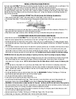
STEP ONE: PILOT LIGHTING (ALL MODELS) 

1. Slightly push in the “

EASY” Safety Valve Knob, 

located behind the ALTERNA™ face plate on the right side (Figure 

32A), and turn clockwise to 

“OFF”


2. Before lighting, wait at least five minutes to allow gas which may have accumulated around burner to escape, then 

slightly push in the “EASY” Safety Valve Knob and turn to 

“PILOT/OFF”


3. Depress Valve Knob until air dissipates and gas flows to pilot (located at center of ATERNA™). Press the 

Piezo  

Igniter Button 

(left side of ALTERNA™) (Figure 33) to light the pilot, and continue to hold Valve Knob in until pilot 

remains lighted after knob is released. The pilot flame should be steady and soft blue surrounding 1/8 inch of the ther-

mocouple tip and extending approximately 1 inch beyond the pilot tube as shown in Figures 34 A and B below. 


NOTE:  

If pilot flame adjustment is necessary, use a narrow long stem flathead screwdriver to turn 

Pilot Adjustment 

Screw 

clockwise for less flame, counterclockwise for more (Figure 32B). If after pilot adjustment the burner begins to 

shutdown, re-adjust for a longer pilot flame.  


4. Slowly turn Valve Knob to “ON” to light burner. (If burner fails to light or if pilot goes out, repeat steps 1 through 4.


5. Adjust the burner flame height by turning the “EASY” Safety Valve Knob clockwise to lower and counter-clockwise to 

raise up to full on (Figure 32).  


6.For complete shutdown, push “EASY” Safety Valve in and turn to “OFF”. 

FIGURE 35 

VALVE PLUG (“ME” MANUAL “EASY”  
CONTROL) SHOWN, ALSO LOCATION FOR;  


• 

ON/OFF SOLENOID (“SE” REMOTE  

        READY MODELS) OR 


• 

DC  MOTOR  DRIVE (“RE” VARIABLE  

        FLAME HEIGHT MODELS) BOTH SHOWN   

        ON FOLLOWING PAGE. 

FIGURE 34 

Piezo Igniter Button 


FULL ON 

NOTE:  

The “

EASY” Safety Valve 

has complete control of gas to  the pilot and burner. It


cannot be turned to 

“OFF” 

without first depressing knob to the 

“PILOT” 

position and then rotating clockwise to 

“OFF”. 

During the heating season 

leave valve knob in 

“PILOT” 

position for convenience. Otherwise, turn to 

“OFF” 

position for any prolonged non-use. 

Periodically check the pilot and burner flame for proper appearance (see page 23  “Customer Responsibilities and  

Maintenance”).  

OFF / LOWER 

B) Pilot Adjustment  

Screw 

A) “EASY” Safety Valve  

  Knob  

C) Knob Position Indicator 

Pilot Location 


FIGURE 33 

IMPORTANT!          KEEP BURNER  AND CONTROL COMPARTMENT CLEAN          IMPORTANT!  

Pilot Assembly 

Air Intake Port 

Piezo Sparker 

Thermocouple 

Tip 

A) 

Pilot Tube 

Blue dot indicating 

Natural Gas or 


Red 

dot indicating 

Propane 

(Right Side) 

(Left Side) 

Summary of Contents for DF-AFB20-ME-N-B

Page 1: ...U S A www rasmussen biz THE GAS LOG COMPANY Do not store or use gasoline or other flammable vapors and liquids in the vicinity of this or any other appliance WHAT TO DO IF YOU SMELL GAS Do not try to...

Page 2: ...before use and at least annually by a professional service person More frequent cleaning may be required due to excessive lint from carpeting bedding material etc It is imperative that control compar...

Page 3: ...3 Wireless Remote Transmitter Devices For SE Models each sold separately A Wireless Hand Held ON OFF Remote SR 2R B Wireless Hand Held ON OFF Remote with Thermostat THR 2R C Wireless Wall Timer 30 60...

Page 4: ...rease the Actual Btu Hr used by the same amount You may also choose to operate your ALTERNA as a Vented Appliance instead See notes and warnings regarding vented installation on Page 7 Adequate Combus...

Page 5: ...plumbing electrical and gas lines and at other openings VENT FREE APPLICATIONS COMBUSTION AIR CALCULATIONS COMBUSTION AIR CALCULATIONS WORKSHEET 1 Room Width Length Height W x L x H Vol ft 1a 1a 1b 1...

Page 6: ...fireplace mantel or facing will not catch fire In most cases they should also be adequate to prevent any discoloration or warping due to heat However each and every decorative gas appli ance installa...

Page 7: ...or remove it completely WARNING CHECK FOR PROPER VENTING A properly sized unobstructed chimney will normally vent all products of combustion Any odor or smoke detected inside the room is an indication...

Page 8: ...and proper gas pressures 2 Seal threads of gas supply with pipe compound then thread 1 2 FIP x 3 8 Flared Elbow Figures 3 and 4A onto the Gas Supply Pipe Figures 3 and 4B and wrench tighten 3 Place Th...

Page 9: ...d row of 3 Full FireBalls on top of the first row with flat side resting against Flame Rod Figures 2A and B FIGURE 6 FIGURE 5 A B Second row with flat side resting against Flame Rod STEP THREE Repeat...

Page 10: ...o the next hole with the tapered end facing down Figure 8 Next place the Cube CU 44 into the third locator hole with the rear right corner resting on the edge of the burner allowing it to lean slightl...

Page 11: ...gure 11 Next place the Cube CU 44 into the third locator hole with the rear right corner resting on the edge of the burner allowing it to lean slightly forward into the locator hole Figure 12 Now plac...

Page 12: ...ightly forward into the locator hole Figure 15 The Fireball FB 4 will fit into the next hole with the tapered end facing down Figure 14 Last place the Cylinder CY 63 into the 1st hole on the right at...

Page 13: ...sponding locator hole Place each FireStone on the 2nd row on top of those on the first row with back side of each resting against Flame Rods see Figure 20 following page WARNING Failure to position th...

Page 14: ...8 Top View FIRESTONES PLACEMENT FOR DF AFS30 cont d Top Row The AFS30 should look like the illustration below when completed ST1 ST3 ST17 ST2 ST20 ST10 ST15 ST18 ST16 ST19 under ST20 ST1 ST3 ST17 ST2...

Page 15: ...ST2 Front View Front View Front View ST1 Top View Bottom Row ST3 ST17 ST2 ST1 ST2 ST3 ST1 ST17 ST3 ST17 ST2 ST1 ST2 ST3 ST1 ST17 FIGURE 22 Top View FIGURE 23 Top View When placing FireStones over eac...

Page 16: ...10 ST3 ST2 ST16 ST1 ST2 ST15 ST18 ST16 ST17 ST10 ST3 ST3 ST10 ST18 ST15 ST16 ST2 ST1 ST17 FIRESTONES PLACEMENT FOR DF AFS24 cont d WARNING Failure to position the parts in accordance with these diagra...

Page 17: ...injury ST17 ST2 Front View Front View ST1 Top View Bottom Row ST17 ST2 ST1 ST2 ST17 ST1 ST17 ST2 ST1 ST2 ST17 ST1 FIGURE 27 Top View FIGURE 28 Top View When placing FireStones over each locator hole c...

Page 18: ...0 should look like the illustrations below when completed ST15 Top View ST16 Front View ST18 Top View Top Row WARNING Failure to position the parts in accordance with these diagrams or failure to use...

Page 19: ...Begin by slowly pouring glass onto the surface of the Alterna being careful not to let any glass drop into the pilot thermocouple or burner areas Figures 31 and 33 Glass in either of these areas may...

Page 20: ...ace screen is closed when the appliance is operating NOTE Any beeping or unexpected shutdown may be the over temperature safety feature in the receiver If this happens move the receiver into a cooler...

Page 21: ...n Valve Knob to ON to light burner If burner fails to light or if pilot goes out repeat steps 1 through 4 5 Adjust the burner flame height by turning the EASY Safety Valve Knob clockwise to lower and...

Page 22: ...ine attaches to the pilot See page 13 Figures 23A and B STEP TWO PILOT ADJUSTMENT ALL MODELS STEP THREE BURNER OPERATION RE VARIABLE FLAME HEIGHT MODELS AND SE REMOTE READY FIGURE 39 FIGURE 37 Slide S...

Page 23: ...rner should be periodically cleaned of debris Use compressed air and or a soft bristle brush to clean burner ports and air shutter area Air shutters should not be altered from factory settings WARNING...

Page 24: ...d Make sure the gas pressure coming into the fireplace falls between the minimum and maximum pressures allowed with this gas set refer to the tables pages 5 and 6 Blocked ports low flame only Free the...

Page 25: ...f incidental or consequential damages so the above limitation or exclusion may not apply to you 3 The maximum liability of RASMUSSEN in connection with this limited warranty shall not in any case exce...

Reviews: