background image

REV.  1/25/08 

Page 4 of 7


INSTALLATION INSTRUCTIONS 


WARNING 


DO  NOT  CONNECT  REMOTE  RECEIVER  DIRECTLY  TO  110-120VAC  POWER.    THIS  WILL  BURN 
OUT  THE  RECEIVER.    FOLLOW  INSTRUCTIONS  FROM  MANUFACTURER  OF  GAS  VALVE  FOR 
CORRECT  WIRING  PROCEDURES.    IMPROPER  INSTALLATION  OF  ELECTRIC  COMPONENTS 
CAN  CAUSE  DAMAGE  TO  GAS  VALVE  AND  REMOTE  RECEIVER.    DAMAGE  CAUSED  BY 
IMPROPER INSTALLATION WILL NOT BE COVERED BY WARRANTY. 


INSTALLATION 

 
The remote receiver can be mounted on or near the fireplace hearth.  PROTECTION FROM EXTREME HEAT IS VERY IMPORTANT.  
Like  any  piece  of  electronic  equipment,  the  remote  receiver  should  be  kept  away  from  temperatures  exceeding  130º  F  inside  the 
receiver case.  Battery life is also significantly shortened if batteries are exposed to high temperatures. 
 

NOTE:  Installation of the receiver in the optional Ceramic Log House (Item# RH2)) is highly recommended. 


HEARTH MOUNT 


The remote receiver can be placed on the fireplace hearth or under the fireplace, behind 
 the control access panel.  Position where the ambient temperature inside the receiver  
case does not exceed 130º F. 
NOTE: Black Button is used on Hearth Mount Applications. 


WIRING INSTRUCTIONS 

 
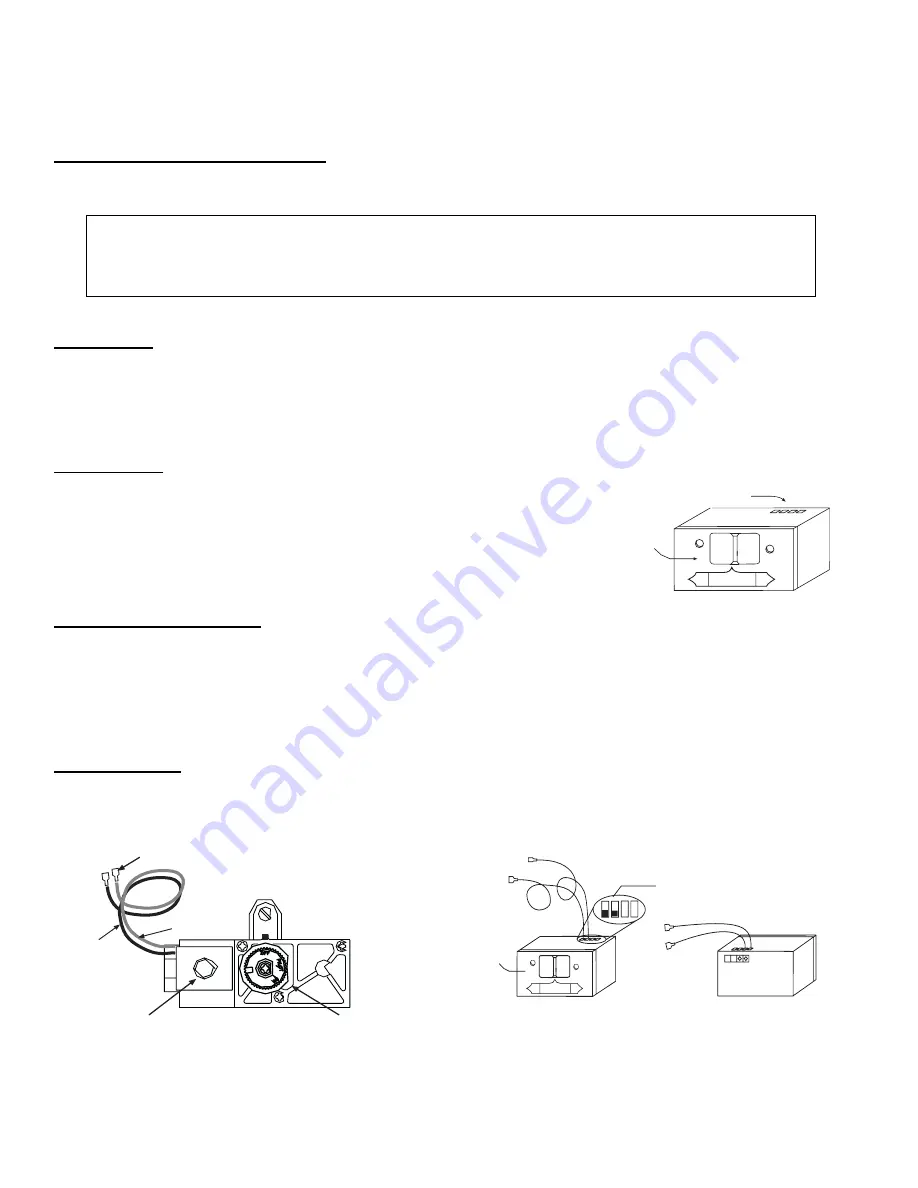
Make sure the remote receiver switch is in the OFF position. For best results it is recommended that 18 gauge stranded wires should 
be used to make connections and should be no longer than 20 ft. 


This THR-2R-1 remote receiver is to be connected to a manual valve with a latching ON/OFF solenoid.  


Connect two 18 gauge stranded or solid wires from the remote receiver terminals to the latching solenoid. (See figure to the right) 
   

IMPORTANT NOTE:

  Operation of this control is dependent on which wire is attached to which terminal.  If operation of control does 

not correspond to operating buttons on transmitter, reverse wire installation at the receiver or at the control. 
 

NOTE

:  Up to 6.3 VDC of power is provided at the receiver terminal. 


 STV-LS

 Solenoid

 1/4” Male

Connectors

 Black Wire

 Red Wire

STV-10

 Valve


Wire terminals

Remote Receiver

Receiver

Slide

Button

LEARN

ADJ.

REMOTE

OFF

ON


Remote Receiver

Receiver

Slide

Button

PULSE MODE

 Terminals

RED Wire

1/4” Female

Terminal

BLACK Wire

1/4” Female

Terminal

(Back of Receiver)

BLACK Wire

1/4” Female

Terminal

RED Wire

1/4” Female

Terminal

LEARN

ADJ.

Part # BPR-3

REMOTE

OFF

ON


f i r e - p a r t s . c o m

Summary of Contents for THR-2R

Page 1: ...he circuit has reversing polarity software which reverses the positive and negative output of the receiver s battery power to drive a latching solenoid ON OFF The SYSTEM is controlled by the remote transmitter The transmitter operates on a 2 1 5V AAA batteries It is recommended that ALKALINE batteries always be used for longer battery life and maximum operational performance Before using the trans...

Page 2: ...n manual on mode OFF OPERATION Press the OFF key the appliance flame will shut off During this time the LCD screen will show OFF After 3 seconds the LCD screen will default to display room temperature and the word TEMP will show THERMOSTAT FUNCTION SETTING DESIRED ROOM TEMPERATURE This remote control system can be thermostatically controlled when the transmitter is in the THERMOSTAT mode The word ...

Page 3: ...ver will respond to the transmitter This is part of the system s design REMOTE RECEIVER IMPORTANT THE REMOTE RECEIVER SHOULD BE POSITIONED WHERE AMBIENT TEMPERATURES DO NOT EXCEED 130 F The remote receiver right operates on four 1 5V AA size batteries It is recommended that ALKALINE batteries be used for longer battery life and maximum microprocessor performance IMPORTANT New or fully charged batt...

Page 4: ... receiver case does not exceed 130º F NOTE Black Button is used on Hearth Mount Applications WIRING INSTRUCTIONS Make sure the remote receiver switch is in the OFF position For best results it is recommended that 18 gauge stranded wires should be used to make connections and should be no longer than 20 ft This THR 2R 1 remote receiver is to be connected to a manual valve with a latching ON OFF sol...

Page 5: ... LOCK OUT CP To activate the LOCK OUT feature press and hold the ON button and the MODE button at the same time for 5 seconds The letters CP will appear in the TEMP frame on the LCD screen To disengage the LOCK OUT press and hold the ON button and the MODE button at the same time for 5 seconds and the letters CP will disappear from the LCD screen and the transmitter will return to its normal opera...

Page 6: ...orrectly installed in the RECEIVER One reversed battery will keep receiver from operating properly Check battery in TRANSMITTER to make sure contacts are touching and ends of battery Bend metal contacts in for tighter fit Be sure RECEIVER and TRANSMITTER are within 20 25 operating range Keep RECEIVER from temperatures exceeding 130 F Battery life shortened when ambient temperatures are above 115 F...

Page 7: ...s transmitter K9LSP1001TH Operating Frequency 303 8 MHZ Canadian IC ID No s transmitter 2439A SP1001TH FCC REQUIREMENTS NOTE THE MANUFACTURER IS NOT RESPONSIBLE FOR ANY RADIO OR TV INTERFERENCE CAUSED BY UNAUTHORIZED MODIFICATIONS TO THIS EQUIPMENT SUCH MODIFICATIONS COULD VOID THE USER S AUTHORITY TO OPERATE THE EQUIPMENT fire parts com ...

Reviews: