5
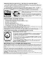
FIGURE 5
PILOT
FLAME
THERMOCOUPLE
1/2 INCH
PILOT FLAME ADJUSTMENT
(TR-18; 24; 30-M-(MANUAL PILOT CONTROL):
PILOT ADJUSTMENT:
1. Pilot flame should be steady and soft blue surrounding
approximately 1/2 inch of the thermocouple tip. (Figure 5)
2. If adjustment is necessary, use a narrow long stem screw
driver to turn PILOT ADJUSTMENT SCREW (Figure 6).
PILOT ADJUST SCREW. (FIGURE 6) Turn clockwise for
less flame, counter clockwise for more flame.
Valve Knob
OFF ON
AT PILOT POSITION
SLIGHT PUSH TO
TURN OFF
FULL PUSH TO
LIGHT
Pilot Adjust
Screw (Located at
base of Valve Stem)
FIGURE 6
TR-18; 24; 30-S-(SWITCH PILOT CONTROL)
LIGHTING PILOT:
1. Slightly push M I L L I V O L T G A S V A L V E Knob. Turn clockwise to
"OFF". (FIGURE 7)
2. Put the C O N T R O L S E L E C T O R S W I T C H into the O F F position.
(FIGURE 7) Accessory Controls must also be turned "OFF". For Remote
Control, put the Remote Receiver Switch in the "OFF" position. For
Thermostat Controlled models, turn temperature dial to "OFF" or to
the lowest temperature setting.
3. Wait at least five minutes to allow gas which may have accumulated
around burner to escape.
4. Slightly push MILLIVOLT GAS V A L V E Knob and turn counter
clockwise to "PILOT". (FIGURE 7)
PILOT
ADJ
Rotate
Valve
Knob
FIGURE 7
MILLIVOLT GAS VALVE
5. Depress and hold M I L L I V O L T G A S V A L V E knob until air is bled and gas flows to pilot. Press P I E Z Z O
IGNITOR BUTTON (FIGURE 8) to light pilot. Continue to depress M I L L I V O L T G A S V A L V E Knob until pilot
remains lit when knob is released (approximately 60 to 90 seconds).
6. If Pilot does not remain lit, repeat steps 1 through 5 and allow more time after Pilot Lighting before releasing
knob.
PILOT FLAME ADJUSTMENT (TR-18; 24; 30-S-
(SWITCH PILOT CONTROL):
PILOT ADJUSTMENT:
1. Pilot flame should be steady and soft blue surrounding
approximately 1/2 inch of the thermocouple tip. (FIGURE 8)
2. If adjustment is necessary, use a narrow long stem screw
driver to turn the PILOT ADJUST SCREW.
PILOT ADJUST SCREW. (FIGURE 8) Turn clockwise for
less flame, counter clockwise for more flame.
FIGURE 8
PILOT
FLAME
THERMOCOUPLE
1/2 INCH
BURNER OPERATION (SWITCH PILOT CONTROL IN MANUAL MODE):
1.
Turn MILLIVOLT GAS VALVE Knob to "ON" (FIGURE 7).
2. To turn burner on, place the CONTROL S E L E C T O R
SWITCH in the "ON" position. (FIGURE 9).
3.
To turn only the burners off (pilot remains lit), place the
CONTROL SELECTOR SWITCH in the : "OFF" position.
NOTE: All three burner's (FRONT BURNER, MIDDLE
BURNER and REAR BURNER) flame height are directly
controlled by the position of the M I L L I V O L T G A S V A L V E Knob
(FIGURE 7).
4.
Complete Shutdown (Including Pilot): Place Control
Selector Switch in "OFF". Turn "OFF" all Accessory
Switches. Slightly push and turn MILLIVOLT GAS V A L V E
Knob to "OFF".
SWITCH OFF REMOTE
ON ACCESS
ON
FIGURE 9
CONTROL SELECTOR
SWITCH
PIEZZO IGNITOR


