background image

6

BURNER OPERATION (SWITCH PILOT CONTROL IN ACCESSORY MODE):

1.  Place Control Selector Switch in the "R E M O T E   A C C E S S   O N " position.  Burner "O N " or "O F F " is now
controlled by the position of the accessory control being used with the burner.  Individual operating instructions for
each Accessory Option are included with the individual accessory.

2.

Complete Shutdown (Including Pilot): Place Control Selector Switch in "OFF".  Turn "OFF" all

Accessory Switches.  Slightly push and turn MILLIVOLT GAS VALVE (Figure 7) Knob to "OFF".

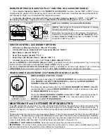
FIGURE 10

To 

ACCESSORY

CONTROL

Control 

Selector 

Switch

Outside Terminal

Outside Terminal

From THERMOPILE

Valve Terminals

THERMO

GEN

SWITCH CONTROL ACCESSORY WIRING :

NOTE: Wire length for Thermostat or Remote or controls
should not exceed 20 feet.

Wiring from the Accessory Control (Remote, Thermostat or
Switch) is connected to the two outside terminals of the
Control Selector Switch as shown in FIGURE 10.  Wire
should be 20 AWG Type CL2.

SWITCH CONTROL ACCESSORY OPTIONS:

Ultra-Sonic Wireless Remote  (Model "F10-AB)

Infrared Wireless Remote With Thermostat (Model "IRRC")

Wall Switch  (Model "WS-1")

Wall Thermostat  (Model "TS-1")

Wall Timer (60 Minute Timer)  (Model "WT-1")

Crackler Sound Generator option for F10 AB  or IRRC (Model "CF5")

Accessory  R E M O T E   L O G   H O U S E   ( M o d e l   " R H " )  is available for use as a heat resistant "log" in which the
receiver portion of Wireless remote option F10 AB  or IRRC may be located.

Accessory  CRACKLER LOG HOUSE (Model "CH") is available for use as a heat resistant "log" in which the
CRACKLER Sound Generator option for both the F10 AB  and IRRC wireless remotes may be located.

REAR BURNER ADJUSTMENT (TOP BURNER CONTROL VALVE):

OFF        ON

FIGURE 11

REAR BURNER

CONTROL VALVE

REAR BURNER CONTROL VALVE:

Once the burners have been lit, the REAR BURNER can be adjusted independently
of the MIDDLE and BOTTOM BURNERS by adjusting the REAR BURNER
CONTROL VALVE (FIGURES 3 & 11)

To achieve the desired flame effect, turn the REAR BURNER CONTROL VALVE
counterclockwise to increase REAR BURNER flame height or clockwise to decrease
the REAR BURNER flame height.

Turning the REAR BURNER CONTROL VALVE to "OFF" will stop all gas flow to
the REAR BURNER CONTROL VALVE only.  Gas will continue to flow to the
MIDDLE and BOTTOM BURNERS.

MAINTENANCE and CUSTOMER RESPONSIBILITIES:

Very little maintenance is required.  The carbon build-up that results from the gas flame is natural and adds to the
realistic appearance of the set.  If carbon becomes excessive it can be lightly brushed or vacuumed away.  If
desired, the logs may  be removed from the firebox and gently sprayed clean with water.  Discoloration from heat is
normal.

Periodically check the pilot burner and main burner flames.  The pilot burner should be free of lint and dirt for best
performance.    Periodically use a brush with stiff bristles to clean pilot.  The main burner should produce a relatively
even flame from side to side.  If not, the sand-granules may have become packed and can be loosened by working
a wire or knife blade under the sand or by refilling the pan as described in the section on

ASSEMBLY AND INSTALLATION. Keep area around log set free and clear from debris.

IMPORTANT. From time to time, examine and clean the venting system.  Once a year, a qualified agency must
examine and clean the venting system of the solid-fuel burning fireplace.

Summary of Contents for TR 3000 SERIES

Page 1: ...M N P 30 SwitchPilotControl PA PR MA NA XF WSA LS UA 36 TR30 S N P WARNING If you do not follow these instructions exactly a fire or explosion may result causing property damage personal injury or loss of life Read these Instructions carefully and retain them for future use THESE APPLIANCES ARE CERTIFIED TO THE FOLLOWING STANDARDS TR 18 TR 24 TR 30 M Manual or S Switch Vented Decorative Appliance ...

Page 2: ... column on LP gases 8 The maximum inlet gas supply pressure shall be 7 inches of water column on natural gas and 14 inches of water column on LP gases 9 The installation and the provision for combustion and ventilation air must conform with the National Fuel Gas Code ANSI Z223 1 Latest Edition 10 The gas log set and its individual shutoff valve must be disconnected from the gas supply piping syste...

Page 3: ...lue MUST BE FREE OF ANY OBSTRUCTIONS 2 Turn off gas supply to fireplace 3 Clean fireplace floor of any ashes 4 Attach damper clamp over edge of fireplace damper blade as shown When installed properly damper clamp prevents accidental full closure of damper See FIGURE 1 If unable to install provided damper clamp consult IMPORTANT INFORMATION on front page of these directions Damper Stop Clamp Damper...

Page 4: ...ion 1 Place lighted match on right side of FRONT BURNER TRAY near inlet end of burner FIGURE 3 DO NOT HOLD MATCH IN HAND 2 Slowly open PRIMARY GAS SUPPLY VALVE and wait for burner to light FIGURE 3 3 Adjust PRIMARY GAS SUPPLY VALVE to obtain desired flame height Ensure adequate gas supply is available to operate FRONT BURNER TRAY and MIDDLE BURNER TRAY TR 18 24 30 M MANUAL PILOT CONTROL PILOT LIGH...

Page 5: ...knob until air is bled and gas flows to pilot Press PIEZZO IGNITOR BUTTON FIGURE 8 to light pilot Continue to depress MILLIVOLT GAS VALVE Knob until pilot remains lit when knob is released approximately 60 to 90 seconds 6 If Pilot does not remain lit repeat steps 1 through 5 and allow more time after Pilot Lighting before releasing knob PILOT FLAME ADJUSTMENT TR 18 24 30 S SWITCH PILOT CONTROL PIL...

Page 6: ...RC wireless remotes may be located REAR BURNER ADJUSTMENT TOP BURNER CONTROL VALVE OFF ON FIGURE 11 REAR BURNER CONTROL VALVE REAR BURNER CONTROL VALVE Once the burners have been lit the REAR BURNER can be adjusted independently of the MIDDLE and BOTTOM BURNERS by adjusting the REAR BURNER CONTROL VALVE FIGURES 3 11 To achieve the desired flame effect turn the REAR BURNER CONTROL VALVE countercloc...

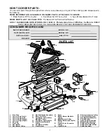
Page 7: ...LER 1 2 3 4 5 6 7 8 9 10 11 12 13 14 15 16 17 18 19 20 21 22 23 24 25 26 27 28 29 30 31 PARTS LIST 1 Pine Cone 10 Gas Distribution Assembly 17 Grate 23 Primary Connector Tubing 2 Top Log Small Left 11 Rear Cover Plate 18 Middle Burner Manifold 24 Control Mounting Plate 3 Top Log Large left 12 Top Burner Control Valve Tubing 25 Gas Regulator Assembly 4 Top Log Small Right Manifold Tubing 19 Middle ...

Page 8: ... RASMUSSEN shall not be liable for any loss damage incidental or consequential damages of any kind whether based upon warranty contract or negligence arising in connection with the sale use or repair of the product Some states do not allow the exclusion or limitation of incidental or consequential damages so the above limitation or exclusion may not apply to you 3 The maximum liability of RASMUSSE...

Reviews: