background image

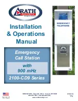
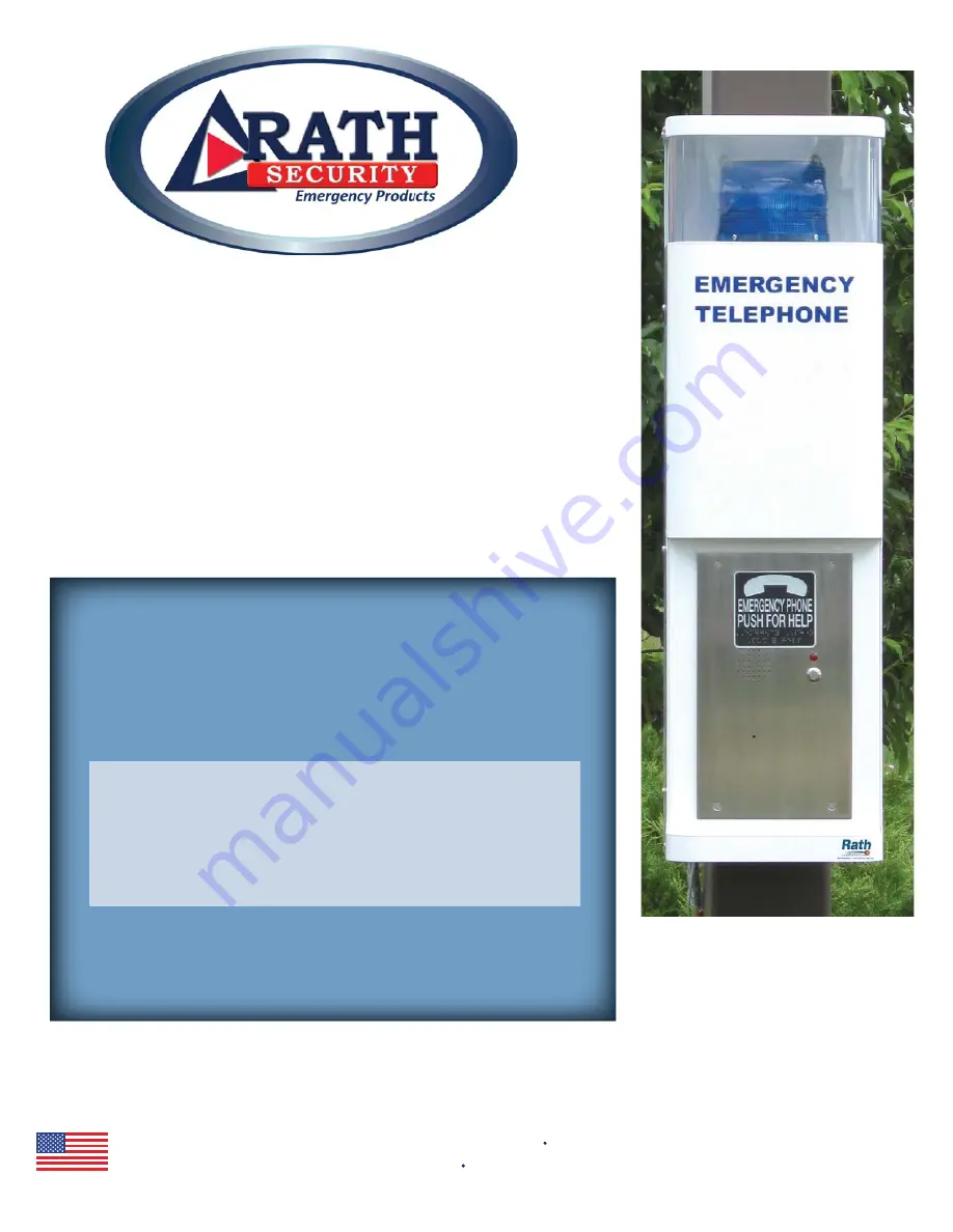
Emergency 

Call Station 

Installation 

& Operations  

 Manual 

Made in the USA 

2 Year Warranty 

2100-CD9 Series 

with 

900 mHz 

11/13 

Ver. 1 

RP8500CD9 

N56 W24720 N. Corporate Circle    Sussex, WI 53089 

800-451-1460    262-246-4828 (fax) 

www.rathsecurity.com  

Summary of Contents for Dusk2Dawn 2100-CD9 Series

Page 1: ...tation Installation Operations Manual Made in the USA 2 Year Warranty 2100 CD9 Series with 900 mHz 11 13 Ver 1 RP8500CD9 N56 W24720 N Corporate Circle Sussex WI 53089 800 451 1460 262 246 4828 fax www rathsecurity com ...

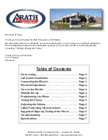
Page 2: ... can rely on Rath to continually provide Innovative Thinking Design and Value Thank you for your business Tom Touchett President Parts Listing Call Station Installation Connecting the Electric Photocell Adjustment Turn on the Electric 900mHz Set Up Programming the Phone Testing the Phone Adjusting the Volume Called Party Hang Up Instructions Suggested Ongoing Testing of the Phone Troubleshooting S...

Page 3: ...ctrical supply conduit 9 Connect the electrical conduit of the 120 277 or 480 volt supply to the call station and run necessary 10 Place the lower plate back into the call station and reinstall the two nuts 11 Install the battery on the lower left side of the call station refer to the diagram below for correct placement 12 Install the transformer on the lower right side of the call station refer t...

Page 4: ...use www rathsecurity com Strobe Phone line 1 4 5 7 8 0 9 6 3 2 Enter Record Play Pause Stop Constant Strobe to 900MhZ Charging Finishing Ready Dusk2Dawn Charging Station 120 VAC Ground Positive Negative y r e t t a B 900 mHz LED for Panel Remote Station FRONT COVER Black will be your positive and white your negative ...

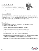
Page 5: ...wer is mounted near a light source Photocell Photocell Cover www rathsecurity com 900mHzSet Up 1 Locate the 900mHz unit with Base Station labeled on the bottom of it 2 Screw black antenna into back of 900mHz Base Station into antenna port 3 Plug dedicated analog phone line or analog extension off of a PBX System into the port labeled Line 4 Connect Power Cable included with unit into DC Input on B...

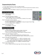
Page 6: ...ss 1 3 Enter 0 Step 4 To exit program mode A Press Stop for 3 seconds REMOTE PROGRAMMING Step 1 To Begin Program mode A Call into phone by dialing the phone number of the tower B After 1st simulated ring Press Wait for 4 tones C Key in security code default is 1111 Wait for confirmation tones Step 2 To Program Emergency Numbers A Press 1 Phone number Wait for confirmation tones Note Emergency numb...

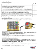
Page 7: ...the Unit Rath recommends that the Emergency Call Station be tested and maintained on a monthly basis to ensure proper operation For testing follow the procedure outlined in Testing of the Phone Rath recommends that the 12 volt battery be replaced every 2 years pg 6 Do you hear a dial tone Does the Strobe start flashing immediately when button was pushed Does red LED become a solid light when you p...

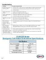
Page 8: ...the appropriate party to make sure the disconnect signal is provided Call station appears non functional Strobe does not flash No audio is heard from speaker when button is pushed Check to make sure phone line is connected between cell unit and phone board Verify 12V to SmartPhone Circuit board Make sure the speaker holes are not blocked Make sure the microphone hole is not blocked Push button may...

Reviews: