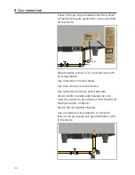
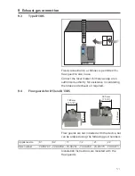
background image

 43

8  Gas connection

8  Gas connection


CAUTION!

Danger to life!
Connecting incorrectly may result in burns.
Observe local regulations.


 DANGER!

Poisoning hazard!
Make sure that factory settings conform with 

actual connection conditions: 
>  Perform exhaust gas analysis when first 

commissioning steam- and convection burn-

ers (CO, CO

2

>   record  these  values. 
If undiluted CO levels are above 150ppm for 

convection and 400ppm for steam, a compa-

ny-trained and certified technician must be 

called in to check burner settings in accordance 

with setting instructions, and adjust these set-

tings if needed.


Observe all local gas company regulations! 

Australian Supplement to Gas Installation
 

>   To be installed only by authorised person in 

accordance with AS 5601, local authority, gas, 

electricity, any applicable statutory regulations 

and manufacturer requirements.


>   Particular attention should be given to rele-

vant requirements regarding ventilation.


>   This appliance is not suitable for use in marine 

environment.

Summary of Contents for SelfCookingCenter

Page 1: ...SelfCookingCenter CombiMaster Plus CombiMaster Original Installation Manual...

Page 2: ...1 Device dimensions 16 5 2 Minimum distances 18 5 3 Securing the device 20 5 3 1 Tabletop units 20 5 3 2 Floor units 26 6 Electrical connection 30 6 1 General information 30 6 2 Electrical devices 32...

Page 3: ...e A3 48 9 2 Type B13 50 9 3 Type B13BS 51 9 4 Flow guards for B13 and B13BS 51 9 5 Maintenance 52 10 Wastewater connection 53 11 Ventilation technical data heat dissipation 56 12 Initial start up 58 1...

Page 4: ...______ ______________________________________ ______________________________________ _____________________________________ Dealer Installer Specify for all queries Appliance model Device no Set to gas...

Page 5: ...the device This installation manual is to be passed on to any subsequent operators of the device Target group The target group for this installation manual are competent technicians who are familiar...

Page 6: ...S SCC CombiMaster Plus CMP CombiMaster CM Appliance size Abbreviation used 6 x 2 3 GN 60 6 x 1 1 GN 61 6 x 2 1 GN 62 10 x 1 1 GN 11 10 x 2 1 GN 12 20 x 1 1 GN 21 20 x 2 1 GN 22 Unit sizes 60 61 62 11...

Page 7: ...hat could poten tially result in serious injury or death CAUTION Possibly hazardous situation that could result in minor injury CAUTION Fire hazard CAUTION Danger of burns CAUTION Corrosive substances...

Page 8: ...er use installa tion maintenance repair or descaling Use of the device for purposes other than those for which it is intended Modifications or technical alterations to the device not authorized by the...

Page 9: ...ial kitchens All other uses are counter to its intended purpose and may be dangerous Gas appliances WARNING Combustion gases When installing under an exhaust hood Switch the exhaust hood on when the d...

Page 10: ...onsibility for their safety To avoid accidents or damage to the device it is imperative that operating personnel receive regular training and safety instructions Explosion hazard WARNING Explosion haz...

Page 11: ...ich are not approved by the man ufacturer void the manufacturer s warranty and product liability Conformity Device conformity is in reference to the over all unit at the time of delivery The operator...

Page 12: ...r To replace the air filter carefully latch the new filter into the correct position Follow the instructions in the Building Equipment and Appliances chapter of the user s manual Unit size 60 Air filt...

Page 13: ...kg 72 111 145 136 189 266 343 SCC Electro lb 159 245 320 300 417 586 756 SCC Gas kg 130 173 159 205 294 381 SCC Gas lb 287 381 351 452 648 840 CMP Electro kg 62 103 147 132 182 254 334 CMP Electro lb...

Page 14: ...60 61 62 11 12 21 22 x mm 880 920 1120 920 1120 950 1150 x Inch 34 3 4 36 1 4 44 1 8 36 1 4 44 1 8 37 1 2 45 1 4 Transporting unit without pallet ATTENTION Risk of damage to the device Only floor unit...

Page 15: ...using carrying straps Note required entrance width Appliance size 60 61 62 11 12 21 22 x mm 630 845 1045 845 1045 925 1145 x Inch 24 6 8 33 1 4 41 1 8 33 1 4 41 1 8 36 3 8 45 1 8 Center of mass Keep t...

Page 16: ...16 5 Setting up the device 5 Setting up the device 5 1 Device dimensions x y z x y z x y z...

Page 17: ...epth y 60 61 62 11 12 21 22 SCC CMP CM mm 623 843 1043 843 1043 909 1114 SCC CMP CM Inch 24 1 2 33 1 4 41 1 8 33 1 4 41 1 8 35 3 4 43 7 8 Height z 60 61 62 11 12 21 22 SCC CMP CM el mm 598 832 832 109...

Page 18: ...erature to the left of the device becomes too high it may trigger an emergency shutdown of the device ATTENTION Device overheating may cause material dam age Do not install fryers onto the back of the...

Page 19: ...ast 500 mm away from left side of the device so that service work can be performed 500 mm 20 Minimum distance to other devices Minimum 350 mm distance between left side of the device and heat sources...

Page 20: ...he cooling air filter Moisture intake may result in device malfunc tions 5 3 Securing the device 5 3 1 Tabletop units For safety reasons tabletop units should only be placed atop a manufacturer origin...

Page 21: ...nting onto an oven stand Insert the two included neoprene blind rivet nuts into the holes in the rear part of the underbody Place the device onto the oven stand Secure in place using the screws provid...

Page 22: ...WARNING Risk of damage injury Secure the gas device against slipping Installing onto an original oven stand use the mounting kit Part number 8700 0317 to attach the stand to the floor either with scre...

Page 23: ...ocks and set the stand up horizontally in the installation location Securing a gas appliance Installing onto an original oven stand a work table or onto the kitchen floor e g Combi Du os Connect unit...

Page 24: ...e not included in delivery and must be ordered separately Movable oven stands base units WARNING Risk of damage injury Damage to electrical or gas lines When mounting onto a rolling base unit or movab...

Page 25: ...25 5 Setting up the device...

Page 26: ...the device 5 3 2 Floor units Make sure the unit is level 10 mm Secure the unit against slipping The enclosed mounting kit may be used to do this 64 5 mm 2 5 8 A Appliance size 21 22 A mm 732 5 937 5 A...

Page 27: ...mounting kit push the floor unit into the foot locks Mobil oven racks Make sure the mobile oven rack is positioned level within the unit ATTENTION Incorrectly aligning the oven rack may cause the dev...

Page 28: ...programme CMP activate the interim cleaning CLE3 clean ing programme Entry ramp If the floor is uneven use an entry ramp to com pensate the unevenness The approach angle must be no greater than 4 WAR...

Page 29: ...g Insert the holder into the left side wall of the unit Remove the side wall to mount the holder Then attach the handle NSF cover panel For hygiene reasons and in accordance with NSF Standard 4 or DIN...

Page 30: ...tor blue neutral conductor brown gray or black phase L1 L2 L3 ATTENTION Improper connection can cause damage to the unit e g fan motor 6 1 General information Only connect the device in accordance wit...

Page 31: ...tion Remove the left side panel to access the connec tion port Removing the left side wall Remove the screws on the bottom of the side panel Pull the side panel down from the device Remove the side p...

Page 32: ...delivered without power cables Cable connection point The main fuse tabletop units or connection ter minal floor units is behind the removable left side panel inside the electrical compartment 6 3 Ga...

Page 33: ...eat Electrical devices Connect a supply cable of at least Type H07RN F and tighten the mains lead cleat Connect the cable according to the following diagram Gray connector terminals L1 L2 L3 independe...

Page 34: ...34 6 Electrical connection 6 5 Equipotential bonding A connection site for optional equipotential bonding is located on the bottom or the back of the device 60 61 62 11 12 21 22...

Page 35: ...6 46 5 36 7 91 6 37 92 9 67 3 168 3 NAC 400V 5 7 8 5 11 16 22 3 32 2 18 6 26 7 36 7 52 7 37 53 4 65 5 95 5 3 AC 400V 11 16 22 3 32 2 19 6 26 7 36 7 52 7 37 53 4 65 5 95 5 3 NAC 415V 6 2 8 7 11 2 16 7...

Page 36: ...4 0 95 7 5 1NAC 220V 0 4 1 8 0 77 3 5 0 5 2 3 0 8 3 7 0 95 4 3 1 6 7 33 1NAC 230V 0 4 1 74 0 77 3 35 0 5 2 17 0 8 3 48 0 95 4 13 1 6 6 96 1NAC 240V 0 4 1 66 0 77 3 21 0 5 2 1 0 8 3 33 0 95 3 96 1 6 6...

Page 37: ...C 400V 10 16 32 32 63 63 100 3 AC 400V 16 32 32 63 63 100 3 NAC 415V 10 16 32 32 63 63 100 3 AC 440V 16 32 32 63 63 100 3 AC 480V 15 32 25 50 50 100 1 NAC 230V 25 50 1 NAC 240V 25 50 2 AC 230V 25 50 2...

Page 38: ...point The CA system separator is supplied for NL and CH and are available through RATIONAL using part number 50 01 820 for other Euro pean countries All other appliances meet the requirements for dri...

Page 39: ...ts Use only new hoses as water connections Do not re use old hoses ATTENTION Non functioning device Ensure that the minimum water conductivity value of 50 S cm Micro Siemens is main tained UK only WRA...

Page 40: ...izes 21 22 3 2 1 Water connection legend 1 3 4 common water supply line cold water up to 30 C 86 F 61 62 11 12 21 22 If split water connection 2 3 4 cold water supply line max 30 C 86 F 3 3 4 soft wat...

Page 41: ...ted to Select Water hardness below 8 75 e Observe all country specific regulations regarding water and sewer connections espe cially those regarding installation of water intake points In most cases w...

Page 42: ...a tion Systems Weak acid decarbonization H ion exchange Sodium ion exchangers as are commonly found in dishwashers are not recom mended Phosphate metering is also not recommended due to its negative e...

Page 43: ...tion and 400ppm for steam a compa ny trained and certified technician must be called in to check burner settings in accordance with setting instructions and adjust these set tings if needed Observe al...

Page 44: ...h local regulations Gas connection internal thread Gas shut off valve on each device Gas connection with gas outlet possible All connection components installed on site must be checked in accordance w...

Page 45: ...ION Device malfunction If line pressure deviates from connection flow pressure 20 contact gas supply company Maintain maximum flow pressure limits 30mbar for natural gas 58mbar for LPG Otherwise do no...

Page 46: ...on at rated thermal load 15 C 1013mbar Wi Ws 12 21 22 Natural gas H G20 18 25 mbar 45 67 50 72 4 87 m3 h 45 kW 4 77 m3 h 44 kW 9 86 m3 h 90 kW Natural gas L G25 20 30 mbar 37 38 41 52 5 76 m3 h 45 kW...

Page 47: ...112 88 0 180 176 Min room size with constant ventilation m3 26 0 56 0 44 0 90 0 88 0 Min combustion air supply m3 h 19 45 35 72 70 144 Max exhaust gas volumes m3 h 38 108 78 180 150 350 Max exhaust g...

Page 48: ...the burners when the exhaust system is in operation Updraft lines are not required To install Type A gas units with total rated loads less than or equal to 14kW it is sufficient if the installation sp...

Page 49: ...ion space greater than 14kW Updraft lines are not required Exhaust gases must be directed outside through kitchen ventilation systems Type A gas applianc es first emit exhaust gases into the room and...

Page 50: ...only be performed with the original flow guards listed below With B13 installations ensure that a vertical updraft line is on hand The updraft line must end 400mm beneath the grease filter The device...

Page 51: ...calculating the intake and exhaust air required 9 4 Flow guards for B13 and B13BS 180 mm 7 1 4 230 mm 320 mm 180 mm 7 1 4 61 11 62 12 21 22 Flow guards are not included with the device but can be orde...

Page 52: ...t to 103 C being triggered in the flow guard Due to high exhaust gas temperatures do not use exhaust pipes made of aluminum or of any materials that are not temperature resistant up to 400 C 9 5 Maint...

Page 53: ...r size 60 units with a constant gradient at least 5 or 3 do not reduce pipe diameter Observe drain dimensioning requirements steam generator short term pump off rate 0 7l s Average wastewater temperat...

Page 54: ...54 10 Wastewater connection Unit size 60 min 3 5 40 mm 1 Unit sizes 61 62 11 12 weight of piping not to be placed on unit drain Air gap per local code Clamped to stand approx 24 3x45 2 copper pipe...

Page 55: ...eight of the water drainage pipe is 70 mm Options Additional riser tube to reduce steam escap ing from drain pipe with open drain systems Tabletop units Increase ground clearance using 110 mm feet and...

Page 56: ...nt of the device Install the device underneath an exhaust hood if using a VarioSmoker Install a grease filter into the protruding part of the exhaust hood Option Exhaust hoods are available for most d...

Page 57: ...0 Gas appliances 61 62 11 12 21 22 latent 2 050 3 450 3 450 6 350 6 850 10 900 sensitive 2 450 4 450 4 450 7 750 8 850 14 000 Thermal load CMP CM devices kJ h Electrical devices 60 61 62 11 12 21 22 l...

Page 58: ...y use containers that are easy to monitor DIN IEC 60335 2 42 The Max rack height for containers with liquid safety decal is included in the starter kit After installing the device attach the decal at...

Page 59: ...k lad ders and the air baffle to ensure they are seat ed correctly The device must be connected to water wastewater and electricity as per installation instructions gas devices must also be con nected...

Page 60: ...60 12 Initial start up DANGER Poisoning hazard With gas units conduct exhaust gas analysis following self test SCC CMP CM...

Page 61: ...sources an additional heat shield can reduce thermal loads 50 mm 2 Appliance size 61 62 11 12 21 22 Left heat shield 60 70 390 60 70 392 60 70 391 60 70 393 60 70 394 60 70 395 Right heat shield 60 70...

Page 62: ...ht adjustable transport trolley for mobile oven rack When using a mobile oven rack and a mobile oven rack transport trolley height differences can be compensated by using an adjustable transport troll...

Page 63: ...alding hazard The topmost rack rail may then be higher than 1600 mm Raising mobile oven racks When using foot extensions on floor units compensate the height difference on the mobile oven rack using m...

Page 64: ...in the mobile oven rack entry area on floor units use an entry ramp to compensate this The plate feet are adjustable by 10 mm The entry ramp is attached to the right foot of the device using the ramp...

Page 65: ...aker can cause the device to malfunction Installing a condensation breaker and the includ ed pipes can divert steam escaping from the exhaust pipe into non critical areas or towards the extraction ran...

Page 66: ...Reducing excessive steam emissions An additional riser pipe can be attached to the exhaust pipe to reduce excess steam emissions The bottom part of the riser pipe has holes in it to create a chimney e...

Page 67: ...only The two devices named above can be attached to the wall using a wall mount ATTENTION Be sure to follow the corresponding modifica tion instructions when performing wall instal lations Appliance...

Page 68: ...60 12 87 01 419 21 22 87 01 420 External signal unit Outlet for connecting an external signal unit optional only for electrical devices unit sizes 61 22 ATTENTION External signal units must not be at...

Page 69: ...22 1 CaO mg l CaCO3 mg l Ca2 mg l 1 dH Germany 10 00 17 86 7 14 1 f France 5 60 10 0 4 00 1 e GB 8 01 14 3 5 72 1 ppm USA 0 56 1 0 0 40 1 mmol l chem cons 56 00 100 0 39 98 1 gr gal USA 9 60 64 8 17 1...

Page 70: ...18 0630 5 50 0 735 20 0700 5 5 55 0 8085 22 0770 6 60 0 882 24 0840 6 5 65 0 9555 26 0910 7 70 1 029 28 0980 7 5 75 1 1025 30 1050 8 80 1 176 32 1120 8 5 85 1 2495 34 1190 9 90 1 323 36 1260 9 5 95 1...

Page 71: ...71...

Page 72: ...80 02 349 V 13 04 2017 RTS Dja en...

Reviews: