20
5. HYDRAULIC INSTALLATION
5.4 INSTALLATION GUIDE
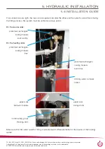
For this purpose please disconnect the:
• 4 hose connections (barriers are provided in
each case),
• electrical connections to the housing (6 plug
connections),
• sensor S5,
• 2 screw connections in the base plate,
• electrical connection to the district heating valve (watch out for the detent of the plug).
The machine is delivered on a pallet in two parts:
• storage module (200 litres of buffer storage including
FriWa and 24 litres MAG)
• hydraulic cooling unit
For easier transport, the refrigeration unit (approx. 80 kg) can
be removed from the hydraulic module.
Summary of Contents for WP Grid-HiQ CF06
Page 1: ...Technical Document state 11 05 2020 WP Grid HiQ CF06...
Page 50: ...50 13 ANNEX 13 1 ELECTRICAL PLAN...
Page 52: ...52 13 ANNEX 13 1 ELECTRICAL PLAN...
Page 54: ...54 13 ANNEX 13 1 ELECTRICAL PLAN...
Page 56: ...56 13 ANNEX 13 1 ELECTRICAL PLAN...
Page 62: ...62 13 ANNEX 13 3 ERROR MESSAGES FREQUENCY INVERTER BONFIGLIOLI AGILE...
Page 64: ...64 13 ANNEX 13 3 ERROR MESSAGES FREQUENCY INVERTER BONFIGLIOLI AGILE...
Page 66: ...66 13 ANNEX 13 4TECHNICAL DATA RSM610...
Page 78: ...78 13 9 LABEL 13 ANNEX...

