Instructions for Use MPR1 DATALOGGER
Manufacturer:
RAUMEDIC AG, Hermann-Staudinger-Strasse 2, 95233 Helmbrechts, Germany
Page 37 of 98
Note: After the connection of sensors to the MPR1 and the start of measurement, you can change the alarm
limit setting for the current measurement (see point
Changing the pressure limiting value).
4.4 Connecting the transducer
The MPR1 has six input channels, to which up to six application units can be connected. As a rule you
need connection cables for the purpose. For this reason, please only use those recommended in the list of
accessories. In individual cases, temperature sensors can be connected directly to the MPR1. All
connections have been arranged on the bottom of the housing, and thus they are drop-proof, if the correct
location is observed, cf.
For the connection diagram, please refer to Fig. 2. All plug-in connectors have been coded mechanically
and colourwise which makes wrong connections impossible. The inputs of the same kind (such as
temperature Temp-1, Temp-2 and invasive pressure P1, P2, P3) have the same rights. No certain sequence
has to be adhered to; pressure sensors of the same kind can be randomly connected to the sockets P1,
P2, P3. The same applies for the temperature sensors and the sockets Temp-1, Temp-2.
For data on the basic settings of the alarm limits, the alarm activation and the settings of the alarm limits,
please refer to chapter 4.9.1 Physiological alarms.
Never use force ! Force will definitely cause damage. When handled correctly, the cable connectors can
be plugged in and removed easily.
Transducers connected are recognised automatically by the MPR1. During the measuring action,
measuring transducers can be added or removed. If and when applicable, measuring locations may be
allocated to the sensors connected (applies for invasive pressure) or the limiting alarm values have to
be set (applies for invasive pressure and temperature).
4.4.1 Operating instructions – connection cable
Plug in or remove the cable always by getting hold at the connector. Never pull the cable.
Do not try to connect a connector with a different mechanical coding in a wrong socket. If something
works stiffly, check once again for safety reasons whether the correct allocation is attempted.
Do not try to open the connectors.
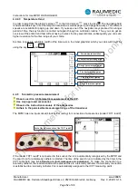
The Redel plugs (all connectors with the exception of the temperature and USB connectors) have been
provided with a push-pull locking system which prevents that the plug-in connections can be removed
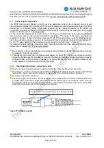
by pulling the cable. To undo the plug-in connection, get hold of the connector in the direct vicinity of the
socket (at the connector part with the two arrow symbols).
Get hold of the connector here! Never get hold on the bush or cable!
Figure 10: Cable connector
This
document
is
for
information
only


