GB
Page 32 of 64
INSTRUCTION, USE AND
MAINTENANCE MANUAL
15.3.4 Static balancing
Make sure there are no stones and/or mud on the
wheel. Remove any counterweights.
Fit the wheel and make sure it is properly fastened
(see par. 12).
Determine the wheel dimensions using the specific
automatic rod (see Par. 15.1.1).
After data entry, close the protection guard to automati-
cally start wheel spin.
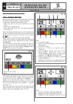
In just a few seconds, the wheel runs at normal speed
and the wheel balancer display shows wheel rotation
(see
Fig. 57
). Do not touch the wheel while taking
measurements. At the end of the spin, the wheel will
stop automatically, taking into account the measured
unbalance so the weight fitting position is at approx.
12 o' clock. Open the protection guard.
Fig. 57
Press in case of emer-
gency
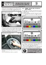
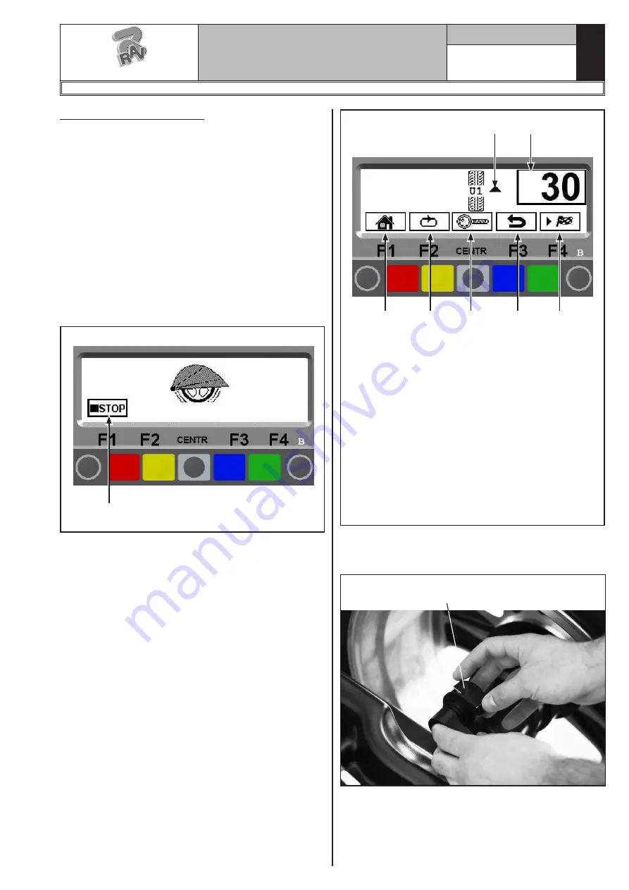
The display unit indicates the direction in which to
move the wheel to fit the weight and how much weight
is needed to correct the unbalance (see
Fig. 58
).
Turn the wheel in the direction indicated by the arrows,
until the correct position is achieved for correction of
unbalance (two horizontal arrows).
Once correct position has been reached, press the
pedal brake to stop the wheel.
Fig. 58
3
4
5
6
7
KEY
1 – Turn the wheel in the direction shown by the
arrows until correct position of the wheel itself
is reached for the weight fitting
2 – Total outer weight to be fitted
3 – R e t u r n t o i n i t i a l p r o g r a m p h a s e
(RED) (F1)
4 – Display next row of keys (MATCHING PROCE-
DURE and HIDDEN WEIGHTS) (YELLOW) (F2)
5 – Displays exact unbalance (resolution 1 g instead
of 5 g) (CENTRAL)
6 – Displays the previous screen page (BLUE) (F3)
7 – Performs spin with protection guard closed
(GREEN) (F4)
2
1
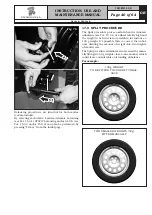
Remove the automatic gauge and fit the adhesive weight
in the pliers as shown in
Fig. 59
, using a weight of pre-
determined value (the example in
Fig. 58
shows 30 g).
Fig. 59
Fit the adhesive weight in the
pliers of the automatic rod
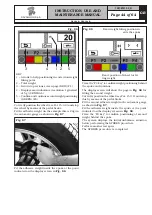
An arrow that appears on the page shows the weight is
coming close to correction position. When two fixed ar-
rows are achieved (see
Fig. 60
) fit the adhesive weight
on the inner side in the position where the weight pliers
touch the wheel.
G2.124R - GP2.124R
RAVAGLIOLI S.p.A.
1297-M010-0_R

