INSTRUCTION, USE AND
MAINTENANCE MANUAL
GB
Page 55 of 64
1
2
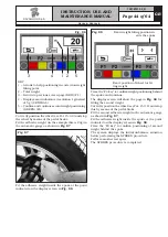
Fig. 114
1
KEY
1 – Exit from the gauge calibration procedure and
return to calibration menu page (RED) (F1)
2 – Perform storing of gauge position on “lower bell”
(GREEN) (F4)
2
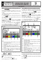
Rest the gauge (
Fig. 115 ref. 1
) down below on the
largest cylindrical part of the bell (
Fig. 115 ref. 2
)
and press the “F4 key”, the program will show the fol-
lowing display page:
Fig. 115
1
KEY
1 – Return to previous screen page (RED) (F1)
2 – Perform storing of gauge position (CENTRAL)
2
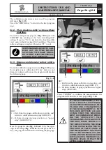
Press “CENTRE” to confirm the measurement
Fit a wheel with ø 15” and set the correct internal
diameter in mm by selecting the
Fig. 116
“PLUS” or
“MINUS” key until the desired value is achieved, then
press "F4” to confirm.
Fig. 116
1297-M010-0_R
G2.124R - GP2.124R
RAVAGLIOLI S.p.A.


