INSTRUCTION, USE AND
MAINTENANCE MANUAL
GB
Page 57 of 64
2 1
2 1
SCREW CHUCK
PNEUMATIC MANDREL
GAR306
1
2
1
2
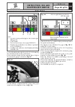
Fig. 120A
SCREW CHUCK
PNEUMATIC MANDREL
GAR304
1
KEY
1 – Exit from the width measurement calibration
procedure and return to calibration menu page
(RED) (F1)
2 – Confirm storing of width measuring device posi-
tion on "end of shaft" (CENTRAL)
2
Fig. 120B
Press “CENTRE” to confirm the measurement. The
program will display the following page:
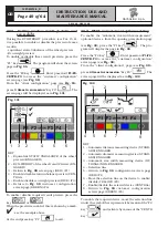
1
KEY
1 – Exit from the width measurement calibration
procedure and return to calibration menu page
(RED) (F1)
2 – Stores width measuring device position on "ex-
ternal flange surface” (CENTRAL)
2
Fig. 121
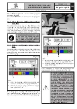
Move the tip of the width measuring device (
Fig. 122A
ref. 1
) in line with the outer surface of the flange
(
Fig. 122A ref. 2
) and press “F4”. The program will
show the screen page in
Fig. 122B
.
1297-M010-0_R
G2.124R - GP2.124R
RAVAGLIOLI S.p.A.


