INSTRUCTION, USE AND
MAINTENANCE MANUAL
EN
Page 21 of 91
9.2.6 Protection guard assembly with auto-
matic width measuring device (stand-
ard on some models)
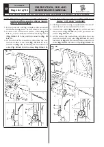
1. Fit the protective casing, complete with automatic
width measuring device, as described in Par. 9.2.5.
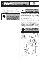
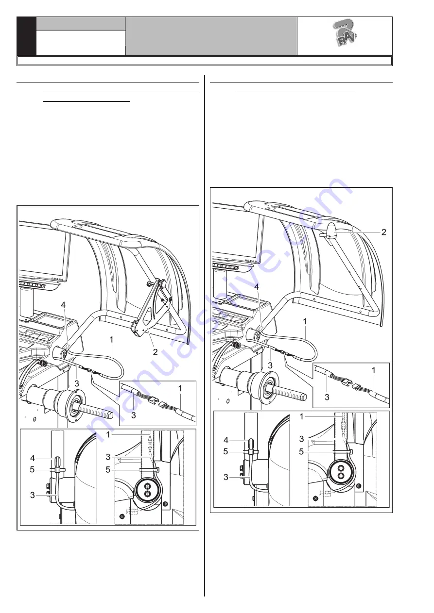
2. Connect the ultrasound sensor cable (
Fig. 19
ref. 1
) of the automatic width measuring device
(
Fig. 19 ref. 2
) to the provided connector (
Fig. 19
ref. 3
).
3. At the end of the connection, introduce the con-
nectors in wheel cover slot (
Fig. 19 ref. 4
), as il-
lustrated in
Fig. 19
.
Eventually, fasten connector’s
cable (
Fig. 19 ref. 3
) with a clamp (
Fig. 19 ref. 5
).
Fig. 19
9.2.7 Protection guard assembly with laser
device "12 o'clock" (optional)
1. Fit the protective casing, complete with 12 o’clock”
laser device” as described in Par. 9.2.5.
2. Connect the cable (
Fig. 20 ref. 1
) of the external
laser device (
Fig. 20 ref. 2
) to the provided con-
nector (
Fig. 20 ref. 3
).
3. At the end of the connection, introduce the con-
nectors in wheel cover slot (
Fig. 20 ref. 4
), as il-
lustrated in
Fig. 20
.
Eventually, fasten connector’s
cable (
Fig. 20 ref. 3
) with a clamp (
Fig. 20 ref. 5
).
Fig. 20
1297-M058-00
G3.150 - GP3.150 - G3.150S - GP3.150S - G3.150WS - GP3.150WS - G3.150WSPLUS - GP3.150WSPLUS - G3.150SA - G3.150WSA
RAVAGLIOLI S.p.A.

