background image


 SERVICE 

MANUAL

 
RAVAGLIOLI  S.p.A. 

RAVTD5040WD / 5060WD / 5080WD  

RAVTD5080WS - RAVTD1760WS/1780WS 

RAVTD1850WS - RAVTD2200WS 

Code R0184 - rev.1.2

(01/2011)


Ravaglioli S.p.A. - 

Via I° Maggio, n° 3 (Frazione di Pontecchio Marconi) 


40037 Sasso Marconi (Bologna - Italy) 


Tel. 051/ 67.81.511 – Fax 051/ 84.64.67 e-mail: rav@ravaglioli.com 


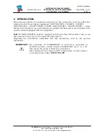
0 INTRODUCTION 

This manual contains the complete instruction for the connections and the calibration, 
relating the RAV wheel aligner equipment “RAVTD5040WD / 5060WD / 5080WD  
RAVTD5080WS - RAVTD1760WS/1780WS RAVTD1850WS - RAVTD2200WS”  series. 
Instructions relating to use and maintenance (skilled the final users) are indicated in the 
specific manual equipped with the equipment. 
 

N.B.

 The RAVTD5040WD model is equipped with the previous SW (version 7.xx), so use 

this manual to refer only to the connections (Chapter 2). 
Regarding the installation, calibration and test procedures, refer to the previous 
instruction. 
  

IMPORTANT!

 The procedure of “CALIBRATION” is reserved to personnel of 

technical services centres licensed RAVAGLIOLI S.p.A. s.r.l. for 
this reason the access is linked by a password.  
Such password, that must be NOT communicate to other person, 
is the sequences of keys “

F8; F7; F6; F8

”. 


Summary of Contents for RAVTD1760WS Series

Page 1: ...ia I Maggio n 3 Frazione di Pontecchio Marconi 40037 Sasso Marconi Bologna Italy Tel 051 67 81 511 Fax 051 84 64 67 e mail rav ravaglioli com FOR USE BY AUTHORISED RAVAGLIOLI S p A AFTER SALES CENTRES WHEEL ALIGNER EQUIPMENT RAVTD5040WD 5060WD 5080WD RAVTD5080WS RAVTD1760WS 1780WS RAVTD1850WS RAVTD2200WS series TEST AND SETTING OPERATIONS AFTER SALES MANUAL ...

Page 2: ...AVTD1760WS 1780WS RAVTD1850WS RAVTD2200WS series Instructions relating to use and maintenance skilled the final users are indicated in the specific manual equipped with the equipment N B The RAVTD5040WD model is equipped with the previous SW version 7 xx so use this manual to refer only to the connections Chapter 2 Regarding the installation calibration and test procedures refer to the previous in...

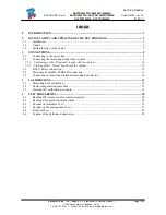
Page 3: ...ne 8 2 2 Connecting the measuring heads to the console 8 2 2 1 Combining of the Bluetooth heads with the cabinet 10 2 2 2 Linking of the Wired heads with the cabinet 12 2 3 R M S device connection 13 2 4 Electronic Turntables STDA43K connection 13 2 5 Connection of sensors and internal measuring head devices 14 3 CALIBRATIONS 15 3 1 Measuring head calibration 15 3 2 Caster compensation procedure 1...

Page 4: ...and finally the ALIGNER AS9 SW IMPORTANT On O S Windows 7 it is necessary before start the SW installation to set the User Account Control U A C it must be set as NEVER NOTIFY Note The PC not provided from factory customer supplying must have the minimum features below indicated CPU clock 1 5 GHz RAM 1 GB HD 80GB 4 USB 2 0 2 serial COM port RS232 or 2 additional USB 2 0 used as RS232 to USB adapto...

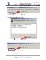
Page 5: ...2 01 2011 Ravaglioli S p A Via I Maggio n 3 Frazione di Pontecchio Marconi Page 3 22 40037 Sasso Marconi Bologna Italy Tel 051 67 81 511 Fax 051 84 64 67 e mail rav ravaglioli com Figure 2 The installation now requires a PC Reboot Figure 3 Figure 4 The installation now requires a second PC Reboot Press Yes Press Install Press Yes ...

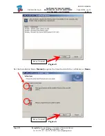
Page 6: ...0184 rev 1 2 01 2011 Page 4 22 Ravaglioli S p A Via I Maggio n 3 Frazione di Pontecchio Marconi 40037 Sasso Marconi Bologna Italy Tel 051 67 81 511 Fax 051 84 64 67 e mail rav ravaglioli com Figure 5 Set the Installation Mode Normal requires the Smartcard with the certificate or Demo Figure 6 Press Install Press Install ...

Page 7: ...m the folder AS9 to C TMLAB ALIGNERS9 System Copy also the security files Token_S9RAV001000011_975e932f39184095922af79ec1c1ed6b enc and X509_S9RAV001000011 cer from the folder AS9 to C TMLAB ALIGNERS9 Security Note the above filenames are for examples S9RAV001000011 is the serial number of the smart card where the file is linked This files are unique and is not possible to copy in another PC for u...

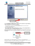
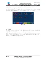
Page 8: ...versa press contemporaneously the keys Ctrl D In a Demo installation it is possible to choose any model between all the range initially appears the above indicated page select the model and press F4 to continue Figure 9 1 2 Update The update software of the RAV Wheel Aligners AS9 series consists of some files including a SETUP EXE file To update the AS9 SW simply made a double click on SETUP exe I...

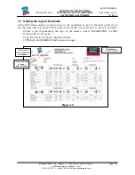
Page 9: ...Setting the logo of the dealer In the RAV wheel aligner program there is the possibility to put in the final printout on the top right side a picture with the logo of the dealer the procedure to set it is as follow Create a file representing the logo of the dealer called DEALER PNG in PNG format 300 x 192 pixel Copy this file in the below indicated folder C TMLAB ALIGNERS9 PrintTemplate images Fig...

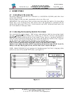
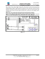
Page 10: ...t to the media or recharge cables 2 2 Connecting the measuring heads to the console The console of the wheel aligner WS series communicates with the measuring heads through a Bluetooth device fitted into a USB port of the PC and the correspondent Bluetooth modules fitted inside the front heads These must be combined together as later described The heads charging are done while the heads are hold o...

Page 11: ...ted to Serial Ports or standard RS232 serial to USB adaptors and linked as later described Front measuring heads do not feature batteries and consequently these cables also provide power The charging of rear heads are done while the heads hare connected to the charging cables See Figure 12 Attention the and poles must be right check this when put the heads on charging If the poles are right the ba...

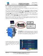
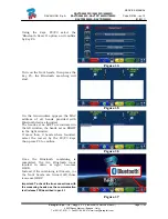
Page 12: ...ds The Bluetooth transmission allow to combine in a univocal way only a single couple of front heads leaving protected by the external interferences and also leaving the possibility to use many Bluetooth aligners in the same place The procedure of Combining described in the following pages is already done in the factory It is necessary only if the customer provide himself to acquire the PC or is n...

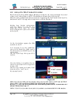
Page 13: ...searching will start Figure 15 On the two windows appears the MAC address of all heads provided with Bluetooth devices founded The heads set as LEFT are indicated in the left window the heads set as RIGHT in the right window If more than 2 heads where founded select the correct by the F2 F3 keys than press F4 to confirm Figure 16 Once the Bluetooth combining is completed the two Bluetooth icons lo...

Page 14: ... then using keys F2 F3 select the Serial Ports Configuration option and confirm by the key F4 Figure 18 On the two windows appears the COM available on the PC It is necessary to set the COM Ports where will be linked the LEFT head in the left window the RIGHT head in the right window Use the F2 F3 keys than press F4 to confirm Figure 19 Once the linking is completed the two serial icons located do...

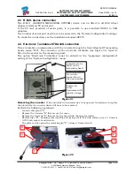
Page 15: ...h the console through the front Bluetooth measuring heads series WS The connector of the electronic turntable see Figure 21 must be fitted in the socket on the measuring head The option Electronic Turntables must be entered in the equipment configuration setting of the System Configuration menu Figure 21 Removing the encoder If the turntable with encoder has to be opened for instance to replace th...

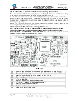
Page 16: ...oards fitted on the measuring heads depending on the model CPU board Code 18253 fitted on the following FRONT heads RAVTD5080WS RAVTD1760WS RAVTD1780WS RAVTD1850WS RAVTD2200WS CPU board Code 18293 fitted on ALL REAR heads and the following FRONT heads RAVTD5040WD RAVTD5060WD RAVTD5080WD This CPU isn t equipped with the Bluetooth devices JP310 and Encoder for turntable connector JP305 Figure 23 JP1...

Page 17: ...ad itself At the time of installation or changing a measuring head the appliance does not therefore require data calibration or configuration Calibration is only required if the transducers are changed or following ascertained repeated errors due to transducer movement as a result of falls knocks etc Use the following calibration systems depending on the models provided 1 STA14 calibration system ...

Page 18: ... F2 F3 select the Additional features option and confirm by key F4 Figure 26 Using the key F2 F3 select the Calibration option and confirm by key F4 Enter the required password to access the calibration phase F8 F7 F6 F8 Figure 27 Using the key F2 F3 select the Measuring Head calibration option and confirm by means of key F4 Figure 28 If required press F3 to enter the serial number for the sensor ...

Page 19: ...nd Level angles are calibrated AFL ARL LFL LRL In stages 3 and 4 the front and rear right hand measuring heads are fitted and the Right Alignment and Level angles are calibrated AFR ARR LFR LRR In stages 5 and 6 the front left hand and front right hand measuring heads are fitted and the Front Toe in and Camber angles are calibrated TFL TFR CFL CFR In stages 7 and 8 the rear left hand and rear righ...

Page 20: ...alibration these sensors are unprovided of TRL TRR The related displays will disappears Figure 31 Legend of the Figure 31 1 Measuring heads on actual calibration step 2 Actual calibration step 3 Calibration steps already acquired 4 Angles calibrated in this step with tolerance reading 5 Value of the angle actually reading 6 Graphic description of the measuring heads positioning on the calibration ...

Page 21: ... necessary set simply by the key F2 and F3 the difference between the front wheel height and the rear wheel height see Figure 33 The system will automatically adjust the caster reading considering this difference relating it with a standard wheel base of the vehicle Figure 33 3 3 Steering Self calibration procedure If the measuring heads are not perfectly calibrated could happen that after the adj...

Page 22: ...he initial logo page press simultaneously the key CTRL F2 will appear the display page of Figure 35 Figure 35 4 1 Reading FW release test for communication On the screen are displayed all the FW version from measuring heads It is possible by this test verify the correct working of the communication between rear to front sensors and from front sensors to console Press the key F1 to exit Figure 36 4...

Page 23: ...les available only with models WS It is possible by this test verify the correct working of the encoders simply turning the upper plate and check that the value displayed correspond to the real angle carried out see Figure 39 The F5 key is used to set to zero the value displayed on the screen Press the key F1 to exit Figure 39 4 4 Encoder on Measuring heads Test On the screen are displayed the rea...

Page 24: ...again and again the one linked on the screen will become of the his real colour an will return uncoloured again see Figure 41 Press the key F1 on the PC keyboard to exit Figure 41 4 6 Counter of the performed aligner test In the initial logo page press simultaneously the key CTRL F12 will appear the counter display page see Figure 42 The meanings is as follow DC Vehicles where Diagnosed Counter RC...

Reviews: