ERVICE
S
54
6823346-R3
FK0345.eps
3.4-2
New Wire Harness
Installation
CAUTION:
Handle the wire harness and its components
with care. Picking up the wire harness by its wires or letting
the load cells hit each other, will damage the connection
between the load cells and wires.
CAUTION:
Use extreme caution and care when installing
the wire harness and its components. Touching wires,
pinched, kinked or sharp bends in wiring will affect the
signal of the load cells.
1
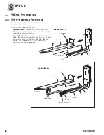
Remove old wire harness as described in Section 3.4-1.
2
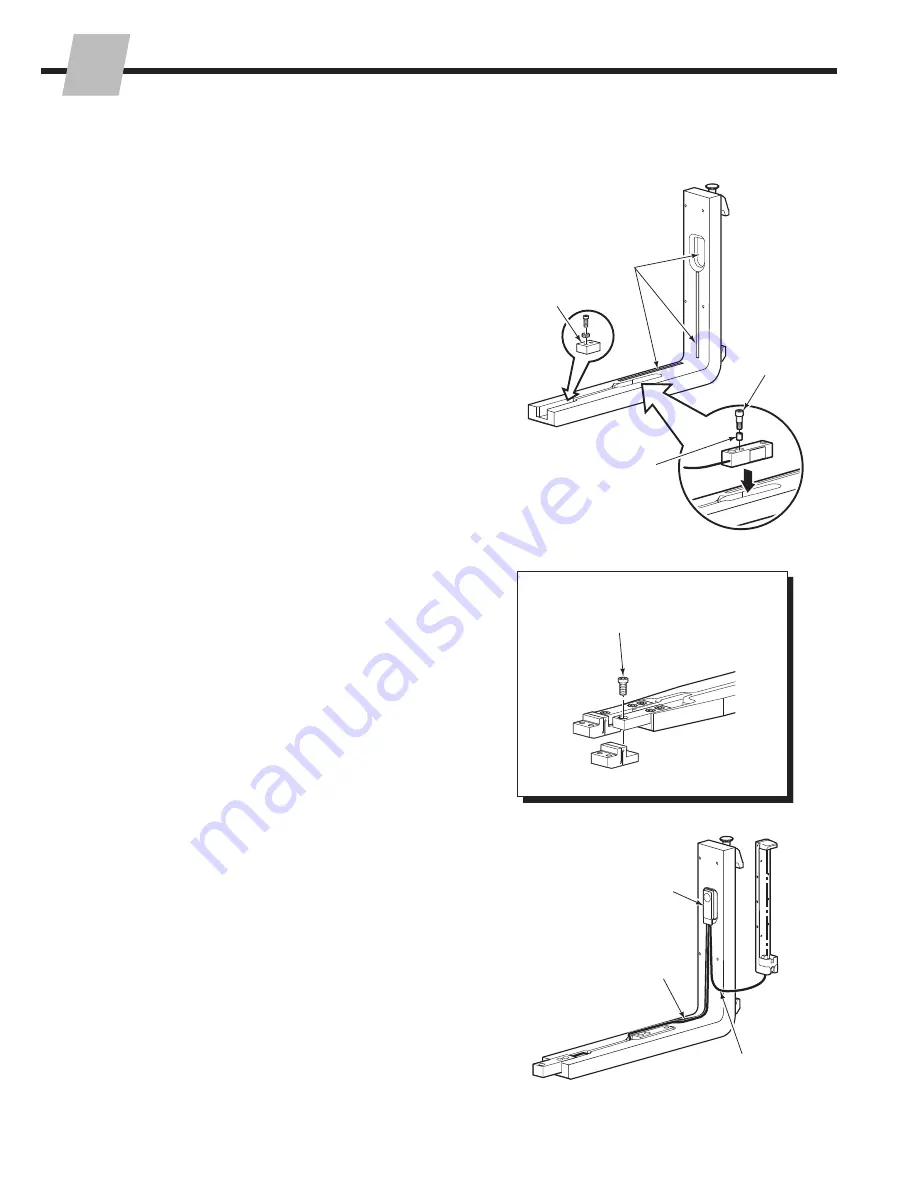
Place new double-sided tape in the fork arm wire
channels and shank cut out.
3
Standard iForks –
Install two tolerance rings to each
load cell.
4
Install load cells and level sensor (if equipped) into fork
arm. Tighten capscrews to the torque of:
Load Cells –
80 ft.-lbs. (110 Nm)
Level Sensor –
2.1 ft.-lbs. (2.8 Nm)
5
Logistic iForks –
Install capscrews mounting the flex
joints to the end load cells. Tighten capscrews to
80 ft.-lbs. (110 Nm).
6
Route wiring in channels to the cutout in the fork shank.
IMPORTANT:
Do not cross the wires over each other.
Touching wires will affect the signal from the load cell
and will cause an error on the display.
7
Install the transmitter in the shank cutout.
8
Route wiring to the battery carrier in the wire channel.
9
Verify that the wires are properly seated by using the
cover plate. The cover plate should not rock side to side
and does not pinch wires.
Level Sensor
2
4
3
4
5
Tolerance Ring
(Standard iForks
only)
FK0335.eps
FK0136.eps
6
8
7


