11
1.
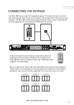
First each unit needs to be addressed using the MASTER/SLAVE switch.
There are 3 positions
for this, Master, Slave 1, and Slave 2 to identify each unit.
2.
Connect the
expansion
OUTPUT of the MASTER unit
to the
INPUT of Slave1
3.
Connect the OUTPUT
of
SLAVE 1 to the INPUT of SLAVE 2.
WWW.RAVETECHNOLOGY.COM
All source audio information - All RS232 control data - All MCU communication from the
master and slave units will be shared through the expansion cable. Each RMC-66P unit
must be connected to the network for APP control.
NOTE
: The MASTER unit IR outputs will function as normal however the IR outputs from
SLAVE1
and SLAVE
2 will not pass through the MASTER IR outputs.
IR flashers from SLAVE
1 and SLAVE
2
zones
will need to added
to source
for IR control
of source devices connected to the MASTER unit.
TRIGGER OUTPUTS
There are 6 trigger outputs corresponding to each zone. When a zone
is powered ON the zone sends 12VDC to the trigger output jack. When
the zone is powered OFF the signal is disengaged. Triggers can be
used to power peripheral equipment ON/OFF with the zones.
ZONE EXPANSION


