background image

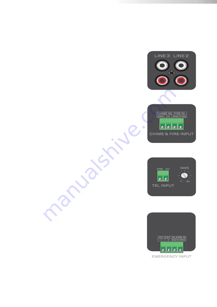
Unbalanced line inputs 2 & 3 (RCA jack):

Line 2 and 3 stereo RCA inputs.

Chime & Fire inputs (Terminal block):

Chime  &  Fire  inputs  can  be  connected  to  any  external   

source, such as call station, signal matrix, fire alarm system. 

The  chime  and  fire  outputs  have  priority  over  all  other 

inputs.

Tel

ephone 

input (Terminal block):

The  amplifier  can  be  connected  to  any  business  telecom 

system using the telephone input, allowing announcements to 

be  made  from  any  handset.  It  is  a  line  level  input  with 

priority,  to  be  connected  to  the  line  output  of  the 

telecom  system.    Unbalanced  input  connections  should  be 

made  to  the  ‘CH’  (Hot  or  Signal)  and  ‘GND’  (Ground) 

terminals.

Emergency input (Terminal block):

The amplifier can be connected to any output of alarm system 

with  24V  DC  remote  control  using  the  emergency  input. 

When the DC 24V input is detected, the amplifier will switch 

all  connected  speakers  (constant  voltage  output)  to  the 

priority alarm output.

Summary of Contents for RPA120

Page 1: ...dia Player 70V 4ohm Compatible 4 Zone 70V Speaker Outputs 6 Input Audio Mixer with Bass Treble Integrated BT Tuner Media Player 3 Microphone Inputs 2 Aux Inputs Fire Alarm Emergency Chime Telephone Inputs Phantom Power 24V DC Battery Power Input 120V AC Power Input Product Featuresoduct Features ...

Page 2: ...E IT OUTDOORS PLACE THE UNIT ON A STABLE BASE OR MOUNT IT IN A STABLE RACK ONLY USE ATTACHMENTS ACCESSORIES SPECIFIED BY THE MANUFACTURER UNPLUG THIS APPARATUS DURING LIGHTNING STORMS OR WHEN UNUSED FOR LONG PERIODS OF TIME ONLY CONNECT THIS UNIT TO A MAIN SOCKET OUTLET WITH PROTECTIVE GROUND CONNECTION READ FOLLOWING INSTRUCTIONS FOR YOUR OWN SAFETY CAUTION This product contains high voltage plea...

Page 3: ...cifications of the original fuse FM antenna When using radio tuner extend the antenna and position upwards for best reception Bluetooth antenna Attach the BT antenna and position it upwards for best reception DC Power Battery Connector The DC power supply 24V connection is to the left of the AC power connector This is used to connect a standby 24V battery A fuse holder with main fuse is located ab...

Page 4: ...A jack connectors This connection can be used when expanding your system Connect additional amplifiers using the OUT of the master amplifier in your setup Balanced line1 mic inputs 1 2 3 combination 6 3 mm XLR jack Channels 1 2 3 are combination connectors accepting both XLR and 6 3 mm jack plugs Both inputs will mute all other channels when a signal is present on the connected microphones inputs ...

Page 5: ...com system using the telephone input allowing announcements to be made from any handset It is a line level input with priority to be connected to the line output of the telecom system Unbalanced input connections should be made to the CH Hot or Signal and GND Ground terminals Emergency input Terminal block The amplifier can be connected to any output of alarm system with 24V DC remote control usin...

Page 6: ... be heard until the fire button is pressed again Two band tone control The overall system frequency response can be adjusted within a range of 12dB Turn the treble and bass knobs left to decrease and the right to increase tone until the desired sound is achieved Microphone echo control Adds echo effect to microphone channels for Karaoke LED indicators The LED indicators correspond to the system ou...

Page 7: ...ker zone outputs 1 4 can be switched on and off by pressing the on off button of the corresponding zone When the zone 1 4 is enabled the on off button will illuminate green to indicate the zone is on When the All button is pressed all zones will turn on or off Zone 1 4 output volume control The output level of each zone 1 4 can be adjusted separately using the individual volume knob of each zone P...

Page 8: ...g on the projects requirements For operating using the low impedance output speakers with a minimum impedance load of 4 ohms or greater can be used 4Ω 8Ω 8Ω OR Example diagram low impedance connections Please note the positive amplifier output should be connected to the positive terminal of the speaker and the ground or negative terminal of the amplifier should be connected to the negative speaker...

Page 9: ...er volume controls on the front and rear panel of the amplifier to their minimum setting Connect all the audio sources to their corresponding channels Turn on the power of the amplifier and all the connected audio sources Set the rear panel input gain levels to 50 then slowly raise the master volume control until the desired sound output level is achieved Depending of the output level of the conne...

Page 10: ...sing the control buttons on front of the device For Bluetooth or Tuner audio press the M mode button to select 5 Bluetooth Adjust the Bluetooth antenna to a vertical position and then press the M button on front to switch the operation mode to Bluetooth Turn on the Bluetooth on your and search for Bluetooth devices you ll find a device named Bluetooth in the list select and connect to it Once you ...

Page 11: ... Cinch For unbalanced line input connections Tip White Signal Left Sleeve Red Ground Right XLR For balanced signal input connections Pin 1 Pin 2 Pin 3 Ground Signal Signal 6 3 mm 1 4 balanced Jack For balanced line in output connections Tip Ring Sleeve Signal Signal Ground 6 3 mm 1 4 unbalanced Jack For unbalanced line in output connections Tip Sleeve Signal Ground ...

Page 12: ...NE OUT TONE CONTROL 70V 70V 50V 35V 25V COM INDICATOR 4 8 OHM OUTPUT 70V DIRECT OUTPUT 70V ZONE1 4 OUTPUT ZONE OUTPUT SELECTION ZONE VOLUME CONTROL PROTECTOR POWER AMPLIFIER MASTER 100Hz 10kHz MUTE MUTE MUTE NORMAL0 NORMAL1 NORMAL2 NORMAL3 NORMAL3 NORMAL2 NORMAL1 NORMAL0 PRIORITY0 PRIORITY PRIORITY 0 1 NORMAL 0 3 INPUT LEVEL GND PHANTOM 24V PRIORITY1 PRIORITY INPUT LEVEL GND INPUT LEVEL PRIORITY0 ...

Page 13: ...nt Voltage Impedance Connectors S ens itivity Connectors S ens itivity Connectors Priority T ype S ens itivity Connectors Phantom power Priority Outputs Indicators LED LCD S ound Fan cooled Clas s A B AC 230V 240V 50 60Hz DC 24V DC Shor t Circuit Over Heating Over Load Limiter Protection Cooling s ys tem Amplifier technology Power s upply Mas ter S tandby OTG 2 0 full s peed controller US B 2 0 T ...

Page 14: ...ply to repairs or alterations made by unauthorized professional This warranty specifically excludes responsibility for consequential damage Retention of your original bill of sale is required to obtain service under the terms of this warranty 2020 Rave Technology All rights reserved All trademarks are the property of their respective owners Specifications are subject to change without notice Rave ...

Reviews: