74
ENGLISH
5.2 TRANSPORTATION
Make sure that the lifting carriage has a payload
higher than the weight of the appliance to be
lifted. The full responsibility of the lifting of
loads lies with the person handling the lifting
equipment.
Ensure wood or timber floors are properly
protected in order to prevent the weight of
the appliance from damaging them during
movement.
During lifting, avoid jerking or abrupt movements.
Pay attention to overbalancing.
6 PREPARING THE PLACE
OF INSTALLATION
6.1 GENERAL CONSIDERATIONS
The following sections contain some guidelines
to be followed to obtain the maximum efficiency
of the product purchased and to ensure safe
operation. The following indications are however
subject to compliance with any possible national,
regional and municipal laws and regulations
in force in the country where the appliance is
installed.
6.2 SAFETY PRECAUTIONS
The operations for assembly and disassembly
of the appliance are reserved for specialist
technicians only.
It is recommended to be sure of their
qualifications and their actual capacity.
6.3 PLACE OF INSTALLATION
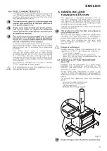
For the minimum distances that must be
respected when positioning the appliance with
respect to flammable materials and objects, refer
to the instructions in Fig. 6.1.
Product images are for illustrative purposes only.
MODEL
X1
X2
Y1
Y2
Z
Apollo
800
mm
300
mm
400
mm
400
mm
1000
mm
Atlas
800
mm
300
mm
400
mm
400
mm
1000
mm
Nova
800
mm
300
mm
500
mm
500
mm
1000
mm
Floors made of flammable material such as wood,
parquet, linoleum, laminate or floors covered
with carpets must be protected by a fireproof
base under the appliance that also protects the
front during cleaning from any falling burning
residues.
The manufacturer declines all responsibility for
any variations in the characteristics of the material
constituting the floor under the protection.
Set up an accessible technical space for any
maintenance work.
Remember to respect the minimum distance
from flammable materials (X), shown on the
identification plate of the pipes used to make the
chimney.
Z
X2
Y1
Y2
X1
Fig. 6.1


