75
ENGLISH
7 INSTALLATION
7.1 GENERAL CONSIDERATIONS
In the following sections some indications are
provided to be complied with in order to obtain
the maximum performance from the purchased
product.
The following indications are however subject to
compliance with any possible national, regional
and municipal laws and regulations in force in
the country where the appliance is installed.
Before proceeding with installation of the
appliance and the execution of the lining, it is
necessary to carry out the following checks:
• check the correct operation of the bypass valve.
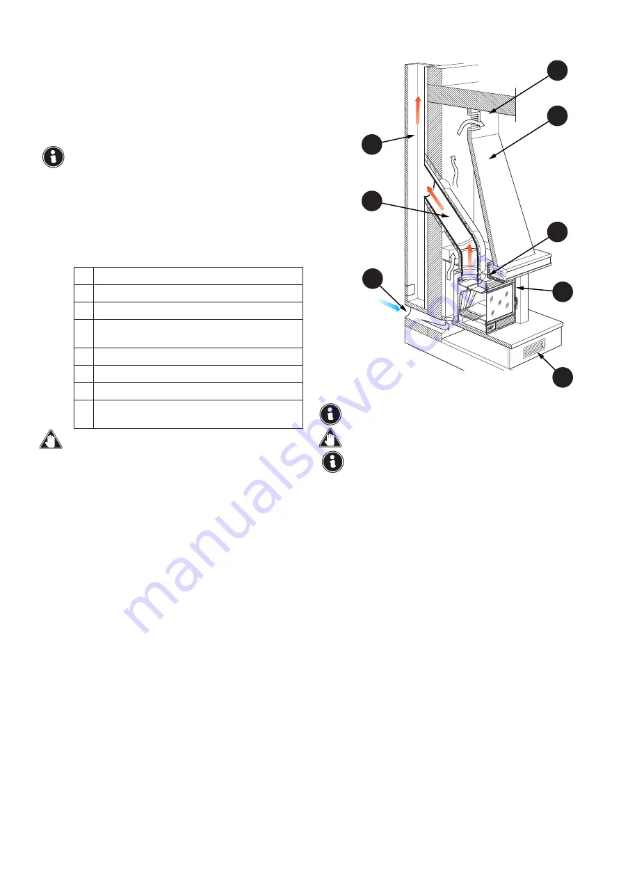
7.2 ASSEMBLY DIAGRAM
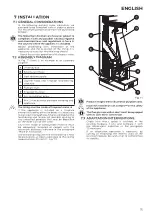
In Fig. 7.1 there is an example of an assembly
diagram.
A
Chimney flue
B
External air intake
C
Heat recovery grate
D
Counter-hood and fireproof load-bearing
structure
E
Flue gas duct
F
Fireproof material
G
Air recirculation grate
H
Min. 5 mm distance between cladding and
appliance
The lining must be made of fireproof material.
If the appliance is installed on a fireplace
previously used by other fire boxes, it is necessary
to carry out thorough cleaning to avoid abnormal
functioning and to prevent possible igniting of
any unburned products that may be deposited
on the inner walls of the same.
Any finish made of combustible material must
be adequately insulated or comply with the
minimum distances indicated in the paragraph
“Place of installation”.
The installation requires the installation of a heat
recovery grate as close as possible to the ceiling
(approximately 20 cm) (C - Fig. 7.1).
Product images are for illustrative purposes only.
Incorrect installation can compromise the safety
of the appliance.
The flue gas evacuation duct must be equipped
with its own earth connection.
7.3 ADAPTATION INTERVENTIONS
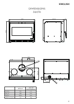
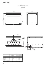
Check how much space is available in the
existing fireplace, if any, and compare it with
the dimensions indicated in the paragraph
“Dimensions”.
If an adaptation operation is necessary, by
cutting or modifying the internal walls of the
existing fireplace, be careful not to compromise
its stability.
Fig. 7.1
A
E
F
C
D
G
B
H


