background image

Pag.20 

This type of installation (see fig. 7) does not require an insulated flue for 
the part inside the house, whilst for the part outside, an insulated tube 
must be used. In the lower part of the flue in the house, a union tee has 
been installed with a peephole, but another one has also been installed 
outside, so that the part can be inspected.
Two 90° bends should not be installed as the ash could quickly block the 
passage of smoke, causing problems for the draught of the stove.

Operating faults due to flue draught problems or critical wea-

ther conditions

Among all weather and geographical conditions that may have an impact on 
the operation of the draught 

fl

 ue (snow, rain, altitude above sl, fog, …) wind 

is certainly the most important. In fact, in addition to the thermal depression 
caused by the temperature difference between the inside and the outside of the 

fl

 ue, there is another type of depression: dynamic depression caused by wind. 

Therefore, wind has an impact on the ef

fi

 ciency of the 

fl

 ue.

THE OPERATION OF THE PELLETS STOVE IS THEREFORE STRONGLY 
DEPENDENT ON THE POSITION AND CONSTRUCTION OF THE FLUE. PRECARIOUS 
CONDITIONS CAN ONLY BE RESOLVED WITH AN APPROPRIATE SETTING OF THE 
STOVE BY RAVELLI APPROVED TECHNICAL PERSONNEL.

7. DESCRIPTION OF THE FUNCTIONING  AND SYMBO-

LOGY OF THE DISPLAY 

The innovation of this particular display is the communication through low volt-
age conveyed waves (12 volts) between the electronic motherboard and  the 
display. The communication is made trough a bipolar cable (ex: the cable for 
the stereo speakers) and the novelty is the possibility to install the display in 
the wall using the optional standard frame for electrical box 503.

7.1. Display with mode “BASE”

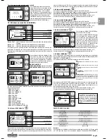
Calender

Room temperature

Clock

Working power

Stove status

Key “1”: 

access key to “set room temperature” and regulation

Key “2”:


access key to “set power” and regulation

Key “OK”:

  short press of the key to confirm and come back to the main 

screen; press the key 3 seconds long to switch on and switch 
off the stove.

The functionalities of this display when used in mode “BASE” are:
• 

Switch on and switch off of the stove

• 

Set of the room temperature and selection of the type of sensor (sup-
plied sensor connected to the motherboard or sensor integrated to the 
display)

• 

Set of the working power (1,2,3,4,5)

7.1.1. switch on and switch off of the stove

Before starting the stove please follow following procedure :

1. 

Connect the power cable

2. 

Set the switch on the backside of the stove on position 1

3. 

Check that the installation is connected to the chimney

4. 

Load the pellet tank with 6 mm pellets

5. 

Load the screw as described in paragraph 8.6

6. 

Press key OK for 3 seconds long.

At this stage the stove will begin the ignition phase.
On the display will appear following writings:
• 

START

 (waiting time is different depending on default settings)

• 

WAITING FLAME

 (waiting time is different depending on default settings)

• 

FLAME LIGHT

 (waiting time is different depending on default settings)

• 

WORK

 (waiting time is different depending on default settings)

7.1.2. Set of the room temperature

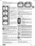
Fig. 1

Fig. 2

The functioning of the stove with room thermostat activated is of 3 types:
• 

With supplied room sensor positioned on the backside of the stove ( not 
available for insert models)

• 

With room sensor integrated to the display

• 

With external thermostat (not supplied)

MODE WITH SUPPLIED ROOM SENSOR (DEFAULT AND SUGGESTED 
USE)  

If you use the supplied room sensor , the display will show the room tem-
perature. To set and modify the room temperature press key number 1 to 
enter in the dedicated menu and set the desired value with key 1 and 2. 
Confirm with key OK 2 times and keep deselected the box SENSOR CON-
SOLLE (flag, see pic.2). Once reached the set temperature the display 
will show  MODULATION WORK, so the stove will reduce to minimum the 
pellet consumption and the power as well.

MODE WITH ROOM SENSOR INTEGRATED TO THE DISPLAY

in case you want to install the display on the wall instead of on the stove 
as from the factory, please reference to the functioning with supplied room 
sensor (as above explicated) with just one difference: the box (flag) 

SEN-

SOR CONSOLLE

, if you work in this mode, should be selected by using 

key 2. Then confirm with the key OK ( reference to pic. 1 paragraph 7.1.2.)

EXTERNAL THERMOSTAT MODE

if you use an external thermostat  correctly connected as shown in the 
electrical scheme ( reference paragraph 10), the display will not show the 
room temperature but the writing T ON ( when the contact is closed) or T 
OFF ( when the contact is open).

REMARK: TO ENABLE THE EXTERNAL THERMOSTAT ENTER IN THE 
SET TEMPERATURE USING KEY 1 AND THEN PRESS REPEATEDLY 
TO REACH THE VALUE “EST” ON THE DISPLAY; CONFIRM TWO 
TIMES WITH THE KEY OK KEEPING DESELECTED THE BOX (FLAG) 

SENSOR CONSOLLE

”.

Once reached the set temperature of the thermostat the display will show  
MODULATION WORK, so the stove will reduce to minimum the pellet 
consumption and the power as well. If activated the mode COMFORT 
CLIMA, the stove will switch on and off automatically (for details reference 
paragraph 8.2.)

1

2

3

5

6

7

8

9

10

4

-TC1+

TERM.

N.AMB.

 SMOKE 

PROBE

ROOM

TERMOSTAT

ROOM

PROBE

-TC1+

TERM.

N.AMB.

N.H2O

N.PEL.

Red

Blue

Black
Black

WE ADVISE A ROOM TERMOSTATE WITH OFF-SET WITH OF MINIMUM 
3°C IF WE WANT ACTIVATE CONFORT CLIMA,PROPERLY.

Insulated 

fl

 ue

Union tee for  conden-

sation of insulation

H > 4 mt

H > 1,5 mt

2-3 metres 

Max

3-5% gradient

Union tee for condensation

Summary of Contents for AURORA CANALIZZATA

Page 1: ...L D EMPLOI EST ENTRETIEN POUR PO LES AVEC TECHNOLOGIE RDS Pour mod les avec carte electronique FLASH DE PELLETHEIZ FEN MIT RDS TECHNOLOGIE GEBRAUCHS UND WARTUNGSANLEITUNG f r Modelle mit FLASH Platine...

Page 2: ...BS ITALY Tel 030 7402939 www ravelligroup it Pag 16 16 16 16 17 17 17 17 17 17 17 18 18 18 20 20 20 20 21 21 21 21 21 21 21 22 22 22 22 22 22 22 22 22 23 23 23 23 23 23 23 23 23 23 24 24 24 24 24 24 2...

Page 3: ...confidence and wishes you happy times in the company of your pellet stove 2 SAFETY INFORMATION The stove must be installed and tested by specialized personnel instructed by the parent company Please...

Page 4: ...exhaust smoke is deviated to wards the stainless steel exchanger 6 and through the smoke extraction tube 4 it is released into the flue through the connection with the smoke exhaust pipe 9 3 6 The com...

Page 5: ...all the smoke pipe has been installed outside the house Height Width Depth Weight Diameter of smoke exit tube Max volume of heating Thermal power Hourly consumption of pellets Electrical power absorbe...

Page 6: ...antee that the ash falls in the union tee with a peephole This type of installation see Fig 5 does not require an insulated flue as all the whole pipe has been assembled outside the house A union tee...

Page 7: ...s described in paragraph 8 6 6 Press key OK for 3 seconds long At this stage the stove will begin the ignition phase On the display will appear following writings START waiting time is different depen...

Page 8: ...y pressing each time the key OK 7 2 4 Menu SET CLOCK To enter in the USER MENU press two times key OK To enter in the menu SET CLOCK press 3 times key 2 and confirm with OK To modify the settings use...

Page 9: ...ey OK To enter in the menu VIEW SET TINGS press 9 times key 2 By confirming with OK you enter in the list of set parameters To scroll the list of parameters use key 1 and 2 To return to the main scree...

Page 10: ...2 To return to the main screen press at the same time keys 1 and 2 Alternatively it is possible to exit by step from the menus by pressing each time the key OK Repeat the operation several times unti...

Page 11: ...cleaner should not be used in direct contact with FIREX 600 Wet cloths should not be used to clean FIREX 600 FIREX 600 is resistant to heat but not to knocks handle with care if moved FIREX 600 may sh...

Page 12: ...e is clear and clean The vacuum switch is malfunctioning Contact local Technical Assistance Centre THERMAL ALARM WITH RESET The thermostat with manual reset has intervened Reset the thermostat pressin...

Page 13: ...HHQ URZQ OXH OXH ODFN OXH ODFN KLWH KLWH KLWH KLWH HOORZ UHHQ URZQ OXH ODFN URZQ OXH HOORZ UHHQ OXH ODFN URZQ KLWH URZQ OXH OXH ODFN ODFN OXH ODFN URZQ OXH OXH OXH QFRGHU 5HG ODFN KLWH URZQ ODFN URZQ...

Page 14: ...Oglio BS ITALY Tel 030 7402939 www ravelligroup it SOMMAIRE 1 Remerciement 2 Informations sur la s curit 3 G n ralit s 3 1 Responsabilit 3 2 Pi ces de rechange 3 3 Fa encerie 3 4 Qu est ce que les gr...

Page 15: ...e vous donner pour obtenir le maximum de votre po le et pour jouir pleine ment de tous les avantages qu il peut et d sire vous donner Nous d sirons ainsi rester proches de nos Clients pour offrir le m...

Page 16: ...des fum es 4 elles sont vacu es dans le conduit des fum es gr ce la connexion effectu e avec le tuyau d vacuation des fum es 9 3 6 La combustion La combustion est une r action chimique dans laquelle...

Page 17: ...est pas n cessaire de respecter des distances de s curit sp cifiques 6 2 Exemples d installation Ce type d installation Voir Fig 9 a besoin d un conduit de fum e calorifug car tout le conduit de fum e...

Page 18: ...ction Ce type d installation Voir Fig 5 n a pas besoin de conduit de fum e calorifug car une partie du conduit de fum es a t mont l int rieur de l habitation et une partie l int rieur d un conduit de...

Page 19: ...trouve derri re le po le dans la position 1 3 V rifier que l implant soit connect avec la chemin e 4 Charger la tr mie avec granul s de bois de 6 mm 5 Effectuer le chargement de la vis sans fin comme...

Page 20: ...ois la touche 2 et confirmer avec OK Pour modifier la programmation faire r f rence au paragraphe 7 1 3 Pour retourner au cran principal appuyer dans la m me temps les touches 1 et 2 On peut aussi sor...

Page 21: ...er 9 fois la touche 2 et confirmer avec OK Pour retourner au cran principal appuyer dans la m me temps les touches 1 et 2 On peut aussi sortir l arri re des menus en pulsant chaque fois la touche OK 7...

Page 22: ...R AU MENU ETAT APPUYER LA TOUCHE OK VOIR PAR 7 2 1 POUR ACTIVER LA VIS SANS FIN LA VIS D ARCHIM DE EST ARR T E LA VIS D ARCHIM DE EST ALLUM E 1 2 Pour retourner dans l cran principal appuyer dans la m...

Page 23: ...n cr ant des points de rupture critiques Il est d conseill d utiliser le tube de l aspirateur en contact direct avec le FIREX 600 Il est d conseill d utiliser des chiffons mouill s pour nettoyer le FI...

Page 24: ...d fectueux Appeler le S A V La combustion dans le brasier n est pas parfaite Eteindre le po le nettoyer le brasier et r gler la combustion avec le r glage des granul s Au cas o cette alarme persiste...

Page 25: ...OHX OHX 1RLU OHX 1RLU ODQF ODQF ODQF ODQF DXQH 9HUW 0DUURQ OHX 1RLU 0DUURQ OHX DXQH 9HUW OHX 1RLU 0DUURQ ODQF 0DUURQ OHX OHX 1RLU 1RLU OHX 1RLU 0DUURQ OHX OHX OHX QFRGHU 5RXJH 1RLU ODQF 0DUURQ 1RLU 0...

Page 26: ...istiques de ses propres produits Ravelli bernimmt keinerlei Haftung f r Fehler in dieser Brosch re und beh lt sich vor die Merkmale seiner Produkte ohne Vorank ndigung zu ndern La sociedad Ravelli no...

Reviews: