25
User’s manual HANDHELD TOUCH RADIO
User’s manual HANDHELD TOUCH RADIO
Pag.28
Pag.29
Vers. 01 of:07.04.14
Vers. 01 of:07.04.14
With this function you can set the level of ducting, therefore, the amount of hot air to be generated in the room where the stove
is installed rather than in the room in which the ducting outlet is installed, with the option to disable it if there is no need for further
heating. Ducting can be set manually or using the automatic function described in this chapter.
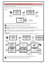
Below are given the steps for accessing the relative menu starting from Stand-By mode.
Press the key
“access menu” to
access the
MENU page
Press the key
“confirm”
to access the
USER page
Press the key
“confirm”
to quickly switch to
DUCTED.
To exit the MANAGEMENT page and return to Stand-by page, press the button repeatedly.
The exit key shows the DUCTED menu to set other variables related to the menu functions.
Single ducting (function present only in models equipped with single ducting system)
Recipe
Press the key
“back to menu” to exit
the page; press the key
“selection” to switch
“AUTO” function.
and activate it with enter
Manual control: the front ventilation is working at the set power. The user can, through a simple operation on display, enable/disable
the ventilation needed for heating the room in which the ducting outlet is installed.
The lines in the table indicate the two ventilations, while the columns indicate the five levels of positioning of the vents.
Press the key
“access menu” to
access the
MENU page
Press the key
“confirm”
to access the
USER page
Press the key
“confirm”
to quickly switch to
DUCTED.
Press the key
“selection” to switch to
VENTILATION function
Ventilation (manual control)
Press the increase/decrease keys
“increase/decrease”
to change the ducting ventilation.
Once you have accessed the function, the top line of the display shows the speed of the front ventilation linked to the power of the
stove (e.g. Front 5), the ducting capacity (bottom line) can be set using the increase/decrease keys; the values can be set from 0 (duc-
ting off) and Auto (ducting capacity adjusted according to front ventilation power); the intermediate settable values are 1 - 2 - 3 - 4 - 5.
To exit the VENTILATION page and return to Stand-by page, press the button repeatedly.
The exit key shows the DUCTED menu to set other variables related to the menu functions.
If you enable the MANUAL CONTROL function, you will not have access to TEMPERATURES or CUBIC CAPACITY
CUBIC CAPACITY. By enabling the AUTOMATIC CONTROL and setting the ducting temperatures you will enable the
stove to automatically control the heat flow.
The stoves with optional fan employ the natural convection system that ensures a considerable heat output in the environment with
the total absence of noise generated by room ventilation. However, the user can activate the optional fan according to the heating
power needed, using the menu below.
Below are given the steps to be followed to access the relative menu from the Standby page.
Press the key
“access to menu” to
open the
MENU page
Press “confirm”
to access the
USER page
Press the key
“confirm”
to go to the option
VENTILATION.
To exit the page and go back to Standby page, press the key for several times.
The exit key opens the VENTILATION menu again to set the other operating parameters available in the menu.
Single ducting (function present only in models equipped with single ducting system)
Control
Control: the ventilation can be set from 0 to AUTO where 0 indicates that the same is disabled; settings from 1 to 5
enable the user to set the fan speed. If the value set is AUTO, the ventilation corresponds to the power
set on the stove.
If the AUTO function is not enabled, the fan operation is not depending on stove’s installed power, except for the cases in
which the flame switches to modulation mode and the heat exchanger is forced to minimum.
Press the keys
“increase/decrease”
to adjust the ventilation.
Chrono function
By activating the chrono function, the user can control the fan speed for each program, as shown in the logic above.
Press the key
“access to menu” to
open the
MENU page
Press “confirm”
“confirm”
to access the
USER page
Press the key
“selection”
to go to the option
CHRONOTHERMOSTAT.
Press the keys
“increase/decrease”
to adjust the ventilation.
To exit the page and go back to Standby page, press the key for several times.
The exit key opens the CHRONO menu again to set the other operating parameters available in the menu.
Press “confirm”
“confirm” upon setup comple-
tion in the following CHRONO
page
USER
USER
DUCTED
DUCTED
CONTROL
DUCTED
SCREW FEEDING
SCREW FEEDING
AIR-PELLET SET
AIR-PELLET SET
CHRONOTHERMOSTAT
CHRONOTHERMOSTAT
MENU
MENU
MANUFACTURER
ENGINEER
MANUFACTURER
ENGINEER
MANUFACTURER
ENGINEER
TEMPERATURE
VENTILATION
VOLUME
DISPLAY STATE
USER
USER
CONTROL
TEMPERATURE
VENTILATION
DUCTED
VOLUME
DISPLAY STATE
MENU
MANUFACTURER
ENGINEER
USER
USER
VENTILATION
SCREW FEEDING
AIR-PELLET SET
CHRONOTHERMOSTAT
MENU
CHRONO
MANUFACTURER
ENGINEER
USER
USER
USER
SCREW FEEDING
SCREW FEEDING
STOVE STATE
STOVE STATE
AIR-PELLET SET
AIR-PELLET SET
CHRONOTHERMOSTAT
CHRONOTHERMOSTAT
ENABLE CHRONO
ENABLE CHRONO
ENABLE CHRONO
ENABLE CHRONO
SET CHRONO
SET CHRONO
SET CHRONO
SET CHRONO
SET CHRONO
SET CHRONO
SET CHRONO
SET CHRONO

