background image

27

User’s manual HANDHELD TOUCH RADIO

User’s manual HANDHELD TOUCH RADIO

Pag.36 

Pag.37 

Vers. 01 of:07.04.14

Vers. 01 of:07.04.14

FLAME

DESCRIPTION

RDS SYSTEM ADJUSTMENT

REQUEST

(only if the RDS system is provi-

ded) 

It shows that the testing procedure and initial parameter calibration have not been comple-

ted or have been performed incorrectly. This indication, however, does not block the stove.

SERVICE REQUEST

The threshold value of set work hours has been reached. The symbol displayed remains

active throughout the work phase. Non-routine maintenance is required on the stove.

AIR FLOW METER FAILU-

RE

(only if the RDS system is provi-

ded) 

It shows a failure of the air flow meter and the stove switches to minimum capacity disabling

the RDS system.

Warning Pop-Up

PHASE

DESCRIPTION

START/RESTART WAIT

Switch-on is requested but with the stove in cooling phase; once this condition is met, it

restarts automatically.

SWITCH ON RESTART

The HOT restart phase is activated.

Functioning is similar to the SWITCH ON phase

HOT SMOKE

The maximum fume temperature threshold has been reached. To facilitate cooling, the

stove brings the capacity to a minimum with ventilation at power level 5, leading to a decre-

ase

in fume temperature.

OFF

The stove is off

WAIT FOR PELLETS

OUT OF

When the switch-on request from ECO-STOP mode coincides with an

automatic switch-off condition (from the TIMER), the stove turns on ensuring total cleaning

of the brazier before switching to FINAL CLEANING.

INFEED SCREW

OVERFLOW

CONDITION: when the pellet setting (set p5) is near the continuous load condition.

SOLUTION: Set the value back to 0.

GENERIC ALARM

The stove is in alarm state; refer to the throubleshooting chapter.

ANOMALY (general)

The stove has detected an anomaly; refer to the throubleshooting chapter.

AUTOMATIC CLEANING 

SYSTEM

ACTIVE

For models with semiautomatic cleaning it indicates the state of the same.

REASON

SOLUTION

• The door and the ash box are not closed correctly

• Make sure they are properly closed.

• Poor combustion in grate.

• Switch off the stove, clean the brazier and check the cleanliness of the

support bench, clean the tube bundle by activating the turbolators. and

adjust the combustion through Pellet/Air settings.

• Presence of foreign body in air intake tube.

• Check for any foreign body and remove it

• The air flow meter may be dirty.

• Clean the flow meter with the stove in "Switched off" state
• Contact the Support Service

SIGNALLING  

RUN

BRAZIER CLEANING

(only if the RDS system is 

provided) 

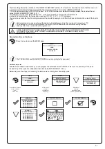
The appearance of the message “ADJUST THE RDS SYSTEM” indicates that the initial parameter testing procedure and

calibration has been unsuccessfully. This indication does not block the stove.

Alarms (table with reference codes)

TRIAL

TITLE

REASON

SOLUTION

AL 01 BLACK OUT

- No voltage during work phase

- Press the switch off key and switch on

boiler switch-on.
- If the problem persists, contact the Support

Service

AL 02 FUME PROBE

- The fume probe is malfunctioning

- Contact the Support Service

- The fume probe is disconnected from the electro-

nic board

- Contact the Support Service

AL 03 FUME OVERTEMP.

- Combustion in the brazier is not optimal due to

clogging or obstructions of internal stove ducts

- Switch off the stove, clean the brazier and the

tube bundle and adjust the combustion setting 

the Pellet/Air values

- The tangential fan (if provided) is

malfunctioning or damaged

- Contact the Support Service

- If the problem persists, contact the Support

Service

AL 04 FUME EXHAUST DAMAGED

- Fume exhaust encoder is not working or is

connected incorrectly

- Contact the Support Service

- No power to fume exhaust system

- Contact the Support Service

- The fume exhaust system is blocked

- Contact the Support Service

AL 05 NO SWITCH-ON

- The pellet tank is empty

- Check for the presence of pellets in the contai-

ner. Top up, if necessary.

- Pellet calibration and suction during switch on

phase is incorrect.

- Contact the Support Service

- The igntition coil is faulty or positioned

- Contact the Support Service

AL 06 PELLETS FINISHED

- The pellet tank is empty.

- Check for the presence of pellets in the contai-

ner. Top up, if necessary.

- The gear motor is not loading pellets

- Empty the tank to see if there are any objects 

inside that may prevent the proper operation of 

the auger.

- Not enough pellets loaded

- Regulate pellets setting from “SET AIR/PEL-

LETS”
- If the problem persists, contact the Support

Service Support

AL 07 RESET THERMAL BREAKER / PELLET 

DOOR OR GATE OPEN 

- The manual reset thermostat has tripped 

connected to the hopper (RESET THERMAL 

BREAKER / 

Pellet door or gate is open 

- Reset the thermostat by pressing the button on 

the back of the stove or close the doors. 

- Combustion in the grate is not optimal due 

to the fact that the grate is clogged or the inner 

stove ducts are clogged. (RESET THERMAL 

BREAKER) 

- Switch off the stove, clean the brazier and the

tube bundle and adjust the combustion setting 

the Pellet/Air values

- Contact the Support Service

AL 08 DEPRESSURIZATION

- The flue is blocked.

Check the flue is free and clean

- The vacuum meter is faulty.

- Contact the Support Service

AL 12 FUME EXHAUST SYSTEM

FAILURE

- T he fume exhaust system has a loss of perfor-

mance due to fan obstruction or voltage drop.

- Contact the Support Service

AL 14 SCREW PHASE

- No cable connection to power the gear motor

of the auger

- Contact the Support Service

AL 15 AUGER TRIAC

- An internal part of the electronic board that 

controls the pellet infeed screw is faulty.  

- Contact the Support Service

- Possible voltage drops or incorrect input voltage  

stove inlet

- Check the mains voltage.

AL 17 NO FLOW

(only if the RDS system is provided) 

- The flow meter does not measure inlet air flow

- Check if the ash pan and door are

  closed correctly and check if the air inlet pipe is 

obstructed.  
- If the problem persists, contact the Support 

Service

AL 19 CLEANER FAILURE

(for models equipped with cleaner)

- The cleaner did not complete the movement and 

is not in the correct position

- Reset the alarm and wait for the stove

to switch to SHUTDOWN mode. Cut off and 

power again, the system reactivates the cleaner 

trying to  search the correct position again.

-- If the problem persists, contact the Support 

Service

Excessive 

Load

Adjust RDS 

system

modulate

Summary of Contents for Dual 7

Page 1: ...nual PLEASE READ THIS ENTIRE MANUAL BEFORE INSTALLATION AND USE OF THIS WOOD PELLET FIRE FAILURE TO FOLLOW THESE INSTRUCTIONS COULD RESULT IN PROPERTY DAMAGE BODILY INJURY OR EVEN DEATH Contact your l...

Page 2: ...echnical programming and individualised air pressure adjustments to ensure it will operate safely and ef ciently and to avoid possible damage to the re or the home Installation of the Dual 7 Wood Pell...

Page 3: ...s 8 2 8 Safety Devices 8 2 9 Responsibilty 8 2 10 Spare Parts 8 3 What are Wood Pellets 9 4 The Components of the Stove 9 4 1 Pellet Combustion 10 5 Maintenance and Cleaning 11 5 1 Cleaning the surfac...

Page 4: ...f the Display 16 6 5 Time and Date Settings 17 6 6 Loading the Auger 18 6 7 Setting Operating Temperature and Power 19 6 8 Turning the Device on 19 6 9 Operating Phases of the Stove 20 6 9 1 Alarms 28...

Page 5: ...f fuel used IMPORTANT The above values were found during testing and may vary with the fuel type climate and installation style Testing Standard Description Class I IP 20 AS NZS 5078 2007 Appliance AS...

Page 6: ...l l a t s n I r e l a e d Solutions Fire personnel who must give the purchaser a declaration of conformity of the appliance and who will installed It is also necessary to take into consideration all t...

Page 7: ...circulation 3 Check clearances to combustibles refer page 37 2 3 Ash The ash content of the fuel and operation of your stove will directly determine the frequency of cleaning The use of high ash fuel...

Page 8: ...ponsibility due to Poor maintenance Failure to observe the instructions in the manual Use not compliant with the safety instructions Installation that is not compliant with the regulations in force in...

Page 9: ...d and can be 1 5 twice greater than that of natural wood The diameter of the cylindrical rods is 6 10 mm and their length can vary between 10 and 50 mm Their weight is equal to about 650 kg m Due to t...

Page 10: ...d Then adjust set pellet air increasing the air percentage from 0 up to 5 If this doesn t work try increasing the loading quantity of the pellet from 0 up to 5 to reach the flame condition shown in pi...

Page 11: ...n i m i t r o f s i h t n o i t a r e g n i k r o w ho l c s t e s y r e v e e m i t e h t e v o t s s i d e n r u t n o 2 s n o i t a t o r y b t l u a f e d d n a r e t f a 8 s r u ean e h T r e 0 6...

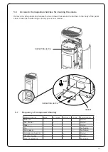
Page 12: ...ime the stove is used and the type of pellet used To access the drawer open the door 2 figure see drawer ashes the extract and 1 figure see N B The operation must be carried out when the stove is cold...

Page 13: ...1 e smontare i laterali come in fig 2 per accedere alle botole di ispezione Le piastre sono guarnizionate pertanto prima di rimontare le botole assicurarsi che le guarnizioni che permettono l ermetici...

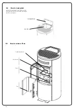
Page 14: ...the iron slide 2 as shown This helps to prevent the pellet bag to touch the cast iron parts Lid of pellet tank Iron slide 1 2 5 8 How to load pellet 5 9 How to remove Firex 7 Opuscolo dedicato modello...

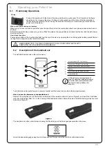
Page 15: ...FRQWDFW ZLWK KRW VXUIDFHV Manuale utente PALMARE IDRO TOUCH RADIO Pag 22 Vers 01 del 07 04 15 Wiring RQQHFW WKH SRZHU FRUG WR WKH EDFN RI WKH VWRYH DQG WKHQ WR D ZDOO VRFNHW 7KH 2 VZLWFK LQ WKH JXUH V...

Page 16: ...VLJQDO IURP WKH KDQGKHOG VHW SUHVVLQJ WKH HQWHU NH RQ WKH KDQGKHOG VHW WKH FRPSRQHQWV VWDUW FRPPXQLFDWLQJ ZLWK HDFK RWKHU FKHFN VLJQ RQ WKH GLVSOD DFFRPSDQLHG E D VRXQG VLJQDO VKRZV WKDW WKH LQLWLDOL...

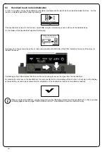
Page 17: ...andheld set Moreover if you press the DOWN scroll key you will display the temperature settings that can be changed using the two UP DOWN keys Any change made is confirmed automatically within 3 secon...

Page 18: ...e Press the key confirm to access the SETTINGS page Press the key confirm to access the USER page Press the key con firm to access the page DATE TIME Press the key selection for selection to switch to...

Page 19: ...le the rotation of the auger The appearance of the message ADJUST THE RDS SYSTEM indicates that the initial parameter testing procedure and calibration has been unsuccessfully This indication does not...

Page 20: ...hermostat optional this must be connected to the appropriate connector on the rear side of the stove and you will have to activate the reading in SETTINGS EN ABLE THERMOSTAT On display appears the wri...

Page 21: ...TA 5 For example with the room temperature at 21 C the stove switches of f when this temperature is reached and restarts when the temperature reaches 15 C 21 C 5 C 0 5 C tolerance You can also activat...

Page 22: ...nge the quantity of pellet loaded in the brazier and the air inflow The stove is tested and inspected with DIN PLUS certified pellets If using another type of pellets or uncertified pellets fuel may n...

Page 23: ...of the stove useful for service during inspection Actual flow Fume extractor revolutions Fume temperature Stove state To exit the STOVE STATE page and return to Stand by page press the button repeated...

Page 24: ...of the information shwon on the handheld set The value can vary from 0 to 100 50 with respect to Settings Firmware version Press the key confirm to access the SETTINGS page Press the key selection to...

Page 25: ...t on the stove If the AUTO function is not enabled the fan operation is not depending on stove s installed power except for the cases in which the flame switches to modulation mode and the heat exchan...

Page 26: ...e WAITING FOR FLAME The pellets ignite and take advantage of the heat in the intake air that passes through the incandescent heater tube FLAME PRESENT The flame is visible in the grate AREAS The stove...

Page 27: ...quest from ECO STOP mode coincides with an automatic switch off condition from the TIMER the stove turns on ensuring total cleaning of the brazier before switching to FINAL CLEANING INFEED SCREW OVERF...

Page 28: ...setting from SET AIR PEL LETS If the problem persists contact the Support Service Support AL 07 RESET THERMAL BREAKER PELLET DOOR OR GATE OPEN The manual reset thermostat has tripped connected to the...

Page 29: ...efore switching on the stove it is necessary to check that the brazier is clean and so that they are always excellent combustion thus avoiding any overheating that may cause changes in the color of th...

Page 30: ...30 38 4 Maintenance Record DATE WORK CARRIED OUT SIGNATURE 40 7 Maitenace record...

Page 31: ...al service fees may apply if you are seeking warranty service from a dealer other than the dealer from whom you originally purchased the product Check with your dealer in advance for any costs to you...

Page 32: ...let Solution e r i F s approved venting components hearth components or other accessories used in conjunction with the appliance Any part of a pre existing replace system Pellet Ravelli i t u l o S on...

Page 33: ...wood pellet re purchase and attach the receipt and any other documents business cards from the retailer that sold you the re Name of Store where Pellet re was purchased Date of Purchase Amount Paid Pa...

Page 34: ...ioning the stove 38 2 6 Location of a power source 38 2 7 Internal Standard Flue Kit 50SBD N 39 2 8 External Standard Flue Kit 51ita 40 2 9 Seismic Restraint 41 2 10 Fixing to Timber Floor Framing 41...

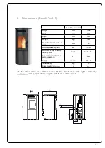
Page 35: ...ter of smoke exhaust duct mm 80 Min max 1040 502 561 power calorofic kW 3 3 6 7 Min max hourly consump tion of pellets Kg h 86 0 95 1 5 Electrical power absorbed during operation W 240 Supply V Hz 220...

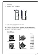
Page 36: ...down completely meaning the likelihood of any hot embers or burning fuel escaping from the combustion chamber is extremely minimal Therefore a 150mm forward projecting floor protector will be suffici...

Page 37: ...H A E External Flue J J F B I F E 7 Dual Pellet Fire Clearance to Combustibles B C A E D G F B F G E Internal Flue Location Dimension mm A B 150 C D E 100 F 0 1 0 G H I J 250 50 n a 50 0 1 0 50 25 Fr...

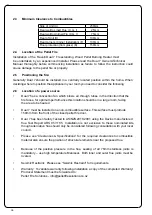
Page 38: ...pellet fire door 7 Dual has been Safety Tested to AS NZS 2001 2918 using the Davins manufactured flue Test Report ARS 05 1185 Installation is not exclusive to these nominated kits though alternative...

Page 39: ...6m The visible flue is finished in black and the ceiling plate is white The support angles for securing the liner to the ceiling are not shown Kit is supplied in a carton Heat resistant floor protect...

Page 40: ...and penetrating the soffit The overall height of the flue is 3 6m All visible flue has a galvanised finish and can be powdercoated on request Kit is supplied in a carton Note The Davin 51 External St...

Page 41: ...5 shall be provided 9 2 Installation 7 Dual should be installed in a centrally located position within the home This will assist the appliance to perform to the level required Dual As heats space by c...

Page 42: ...42 1 2 x 4 2 12 How to mount the side panels 10 Opuscule d di au mod le Dual 7 Brochure for Dual 7 model Brosch re f r Modell Dual 7 2 3 x 4...

Page 43: ..._________________ Phone ________________________________ Model __________________________ Serial Number ____________________ Date of Purchase __________ dd mm yy Date of Installation _________ dd mm y...

Page 44: ...44 38 4 Maintenance Record DATE WORK CARRIED OUT SIGNATURE 40...

Page 45: ...peration of my Pellet Fire I understand that warranty conditions require an authorised Pellet Fire Solutions Installer to complete the installation Signed Date Installation Details Pellet Fire Model S...

Reviews: