


Manuale uso e manutenzione S70- S90- SC90
Pag.41
Rev.0 18/05/2020
The first setting allows the activation of the CLIMATE COMFORT function. This function is intended to ensure that the room tem
perature set is maintained steady upon setting the maximum period of “X” minutes (SWITCH-OFF DELA Y: 5 MIN) before switch-ing
to ECO STOP phase. The STOVE maintains this state until the temperature drops below the set value (CLIMATE COMFORT DELTA:
5°C). For example, with the room temperature at 21 ° C, the stove switches of f when this temperature is reached and restarts when
the temperature reaches 16°C (21°C - 5°C). You can also activate the function using an external thermostat, keeping in mind that this
does not include the value of hysteresis.
Setting
Below are the steps to follow, starting from the Home screen, to access the Home menu.
After following the above procedure
Settings > Enable thermostat
Manuale utente PALMARE IDRO TOUCH RADIO
Manuale utente PALMARE IDRO TOUCH RADIO
Pag.30
Pag.31
Vers. 01 del 07/04/15
Vers. 01 del 07/04/15
Below are given the steps for accessing the relative menu starting from Stand-By mode.
Stove State
Press the key
“access menu” to
access the
MENU page
Press the key
“confirm”
to access the
USER page
Press the key
several times
to quickly switch to
Stove STATUS.
To exit the STOVE STATE page and return to Stand-by page, press the button repeatedly.
In this mode you can check the proper operation of the most important parameters of the appliance. Here is a list of real data of the
stove useful for service during inspection.
- Circulator state (ON running)
- Position of 3-way valve DHW (domestic hot water) or HEAT (heating);
- System pressure;
- Stove state;
- Current boiler power;
- Flow read by the flow meter;
- Fume extractor speed;
- Actual flow set;
Settings > Enable thermostat
Press the “enter” key
to access the
SETTINGS
Press the key
“selection” to switch to
ENABLE THERMOSTAT.
Press the key
“confirm”
to access the function
Press the key
“confirm”
to enable the function.
In Stand-By mode, instead of room temperature measured
and settable, appears the line T ON if the room in which
the thermostat is installed has not reached the temperature
requested or the writing T OFF if the temperature in the
room is reached.
Press the key for several
times
to return to
“STAND BY” page
- Temperature read by the handheld unit;
- External thermostat (request ON);
- Flame temperature (combustion chamber);
- Combustion fume exhaust temperature;
- Inlet flow meter temperature;
- Heated flow meter temp.;
- Electronic board temperature;
- Boiler water temperature (SUPPLY);
- Boiler water temperature (optional) - RETURN from the system;
- Boiler DHW temperature;
- Puffer temperature - average warm point;
- Puffer temperature second reading (low temp.).
Below are given the steps for accessing the relative menu starting from Stand-By mode.
Settings
Press the key
“access menu” to
access the
MENU page
Press the key
“confirm”
to access the
USER page
Press the key
“selection” to switch to
second menu page
to the function
SETTINGS.
After following the procedure above step by step, you can set the following functions:
Settings > Contrast
Press the key
“confirm” to
access the
SETUP
SETTINGS
Press the key
“selection” to switch
to the function
CONTRAST.
Press the key
“confirm”
to access the function
Use the UP/DOWN keys to change contrast setting and obtain
a better visualisation of the information shown on the handheld
set.
The value can vary from 0 to 100. 50 with respect to the
standard value.
By pressing the following key you will confirm of data
and switch to the page within SETTINGS menu.
Settings > Season
Press the key
“confirm” to
access the
SETUP
SETTINGS
Press the key
“selection” to switch
to the function
CONTRAST.
Press the key
“confirm”
to access the function
Use the UP/DOWN keys to change the WINTER/
SUMMER season. Function that can be set when
working with DHW puffer (Boiler).
See chap. Evolved hydraulic diagrams
By pressing the following key you will confirm of data
and switch to the page within SETTINGS menu.
Press the “enter” key to
access the
SETTINGS
Press the key
“selection” to switch to
CONTRAST.
Press the key
“confirm”
to access the function
Settings > Firmware version
By pressing the button you will confirm the data and switch to the page within the SETTINGS menu.
MENU
STOVE STATE
STOVE STATE
STOVE STATE
STOVE STATE
USER
ACTIVE PARTS
ACTIVE PARTS
ACTIVE PARTS
ACTIVE PARTS
ACTUAL STATES
PUMP
PRESSURE 1.1 BAR
SHUTDOWN
POWER MOD
HH T …
EXT.T …
FLAME T 340°C
FUME T 120°C
F. EX. T 30°C
C. EX. T 55°C
EL B. T---25°C
T. CALDERA
T.PUFFER H
T.PUFFER L
3-WAY VALVE HEAT
ACTUAL STATES
ACTUAL STATES
ACTUAL STATES
H20 TEMPERATURE
H20 TEMPERATURE
v
H20 TEMPERATURE
TECHNICIAN
STATE TEMPERATURE
STATE TEMPERATURE
STATE TEMPERATURE
STATE TEMPERATURE
USER
USER
POWER SETTING
STOVE STATE
CHRONOTHERMOSTAT
COMFROT CLIMA
SCREW LOADING
SETTING
SET AIR-PELLET
DATE-TIME
DATE-TIME
DATE-TIME
DATE-TIME
DATE-TIME
WINTER
CONTRAST
FIRMWARE
SUMMER
DATE-TIME
ENABLE THERMOSTAT
ENABLE THERMOSTAT
ENABLE EXT. T
ENABLE EXT. T
ENABLE EXT. T
ENABLE EXT. T
ENABLE EXT. T
ENABLE EXT. T
SEASON
SEASON
SEASON
SEASON
SEASON
SEASON
CONTRAST
CONTRAST
CONTRAST
CONTRAST
CONTRAST
CONTRAST
FW VERSION
FW VERSION
FW VERSION
FW VERSION
FW VERSION
FW VERSION
LANGUAGE
LANGUAGE
LANGUAGE
LANGUAGE
LANGUAGE
LANGUAGE
ADJUST
ADJUST
ADJUST
ADJUST
ADJUST
ADJUST
DATE-TIME
ENABLE EXT. T
SEASON
CONTRAST
FW VERSION
LANGUAGE
ADJUST
DATE-TIME
ENABLE EXT. T
SEASON
CONTRAST
FW VERSION
LANGUAGE
ADJUST
MENU
USER
TECHNICIAN
USER
USER
POWER SETTING
STOVE STATE
CHRONOTHERMOSTAT
COMFROT CLIMA
SCREW LOADING
SETTING
SET AIR-PELLET
MANUFACTURER’S
MANUFACTURER’S
📌
In “Home” mode, instead of room temperature measured and settable, appears the line T ON if the room in which the
thermostat is installed has not reached the temperature requested or the writing T OFF if the temperature in the room is
reached.
User’s manual HANDHELD TOUCH RADIO
User’s manual HANDHELD TOUCH RADIO
Pag.22
Pag.23
Vers. 01 of:07.04.14
Vers. 01 of:07.04.14
Loading the auger
MENU
USER
SCREW FEEDING
SCREW FEEDING
CHRONOTHERMOSTAT
AIR-PELLET SET
STOVE STATE
USER
MANUFACTURER
ENGINEER
MENU
USER
MANUFACTURER
ENGINEER
USER
USER
COMFORT CLIMA
COMFORT CLIMA
COMFORT CLIMA
COMFORT CLIMA
ENABLE COMFORT
ENABLE COMFORT
ENABLE COMFORT
RESTART DELTA
RESTART DELTA
SHUTDOWN DELAY
SHUTDOWN DELAY
SHUTDOWN DELAY
SHUTDOWN DELAY
ENABLE COMFORT
ENABLE COMFORT
COMFORT CLIMA DELTA
COMFORT CLIMA DELTA
RESTART DELTA
SHUTDOWN DELAY
SETTINGS
SCREW FEEDING
CHRONOTHERMOSTAT
AIR-PELLET SET
STOVE STATE
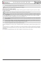
ALWAYS EMPTY THE BRAZIER BEFORE TURNING THE STOVE ON AND ALWAYS CHECK
THAT ALL NONE OF ITS HOLES IS CLOGGED NEVER EMPTY THE RBAZIER INSIDE THE HOPPER.
FIRE HAZARD.
Carry out this operation to facilitate stove’s first start operations; You should also check that you have introduced pellets
into the hopper and wait until the stove is in “SHUTDOWN” or “FINAL CLEANING” mode. The number expressed in sec-
onds indicates the rotation time of the infeed screw during the first loading cycle. Once this time has elapsed, the infeed
screw stops immediately and then pellets are emptied from the grate before turning on the equipment.
Below are given the steps for accessing the relative menu.
Press the key “access
menu” to access
the
MENU page
Press the key
“confirm”
to access the
USER page
At the end of the auger loading, the display shows 0 “and automatically switches to the USER menu page.
Press the key for several times until the Stand-by page is displayed.
Setting operating temperature and power:
Set the two values following the indications given in the chapter “Description of thr display”
Turning the device on
Keep the key ON/OFF pressed for a few seconds to turn on the stove.
Press CONFIRM to enable
the rotation of the auger
The appearance of the message “ADJUST THE RDS SYSTEM” indicates that the initial parameter testing procedure
and calibration has been unsuccessfully. This indication does not cause stove blockage (see the SIGNALLING POP UP
section).
On the display of the handheld set appears the following:
Press and hold the ON/OFF button to turn off the stove door, and reset any alarms triggered.
In case the infeed screw operations described avobe have not been executed, the stove may fail to turn on. In this case,
carry out the operations described above and empty the brazier and reset the alarm.
If the stove still fails to turn on, check that the grate is properly installed and perfectly adherent to the base, and also check that
there are no deposits that prevent the smooth passage of air to enable ignition. If the problem persists, contact the support ser
-
vice.
Sequence of ignition phases
SWITCH-ON- initial pellet loading phase;
WAIT FLAME - flame
development wait
phase;
FLAME PRESENT - flame stabilization
phase and reduction of combustible
inside the brazier;
What happens if the batteries are empty?
If the battery is discharged, within the
“drop” is shown a symbol that indicates
that the battery is empty, while maintain-
ing active the features of your device.
WORK - operation phase
described in
the dedicated chapter;
As soon as the level of the battery
prevents the radio communication the
handheld set displays on full screen the
picture of empty battery and all device
functions are locked until the batteries
are replaced
CONNECT AN EXTERNAL THERMOSTAT WITH A SIMPLE DRY CONTACT, THEREFORE, NOT POWERED. MORE-
OVER, WE RECOMMEND YOU USE A THERMOSTAT WITH A MINIMUM OFFSET OF 3°C IF YOU INTEND TO USE
THE COMFORT CLIMA FUNCTION.
Operating phases of the appliance
Modulation
During the work phase, the appliance should reach the room temperature set; when this condition is met, the stove switches to
MODULATION mode in which fuel consumption and ventilation are minimum.
If you wish to detect the ambient temperature by means of an external thermostat (optional), this must be connected to
the appropriate connector on the rear side of the stove; and you will have to activate the reading in “SETTINGS - EN -
ABLE THERMOSTAT.” On display appears the writing TON / TOFF based on thermostat request.
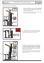
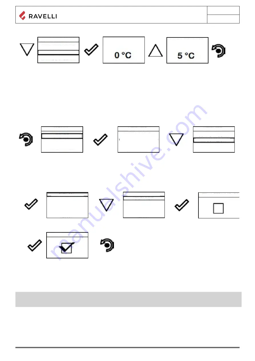
Comfort climate
The activation of this function enables the stove to reduce pellet consumption by activating the modulation phases, after the desired
temperature has been reached. Subsequently, the stove checks that the temperature is maintained steady for a preset time. If this
condition is met, it automatically switches off, and on display appears the writing ECO.
The stove turns on again when the temperature drops below the set threshold.
Below are given the steps for accessing the relative menu.
Press the key
“access menu” to
access
the
MENU page
Press the key
“confirm”
to access the
USER page
Once you have accessed the Climate Comfort menu, it is possible to operate on the 3 types of settings dedicated to the function:
Press the key for several times until the Stand-by page is displayed.
Press the key “selection” for
“selection”
to switch to the second page
of USER MENU and select
CLIMATE COMFORT.
User’s manual HANDHELD TOUCH RADIO
User’s manual HANDHELD TOUCH RADIO
Pag.20
Pag.21
Vers. 01 of:07.04.14
Vers. 01 of:07.04.14
2
3
1
2
3
1
FIRST INSTALLATION?
PRESS THE KEY RADIO
ADJ ON THE STOVE
YES
MENU
USER
USER
SETTINGS
SETTINGS
DATE-TIME
USER
COMFORT CLIMA
MANUFACTURER
ENGINEER
ENABLE EXT. TH.
CONTRAST
FW VERSION
ADJUST
LANGUAGE
SCREW FEEDING
CHRONOTHERMOSTAT
AIR-PELLET SET
STOVE STATE
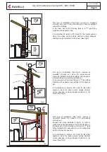
Handheld touch radio initialization
In order to operate correctly, the handheld set should be interfaced with the electronic board installed inside the stove. For this
reason, on display appears the following message:
If the handheld set is used for the first time, select
YES
using the selection keys and confirm with the dedicated key.
On the display of the handheld set appears the following:
Hold down for a few seconds the button of radio communication (RADIO ADJ) of the PCB, located on the back of the stove, to
initialize the device.
The flashing yellow LED indicates that the circuit board is waiting to receive the signal from the handheld set.
By pressing the enter key on the handheld set, the components start communicating with each other. A check sign on the display,
accompanied by a sound signal, shows that the initialization of the handheld set has been completed sucessfully
.
When you replace the batteries, you do not have to run the initialization procedure of the handheld set. In this case, when
on display appears the message “FIRST INSTALLATION ?”, select
NO
and press the confirmation key.
Description of the display
The display of the handheld set is described below (in stand-by mode):
After 5 minutes of inactivity, the display of the handheld set turns dark, switching to “SLEEP” mode, while maintaining the
radio connection with the stove. By pressing the key ON/OFF, the display becomes active again.
The first pressure of any key with the display active, lights up its backlight, but it is not, however
,
considered a command.
The display is subdivided into three parts:
1. It shows the current room temperature measured by the handheld set. Moreover, if you press the DOWN scroll key you will
display
the temperature settings that can be changed using the two UP/DOWN keys. Any change made is confirmed automatically
within 3 seconds from the change or by pressing the confirmation key. A sound signal indicates that the change has been con
-
firmed.
In the inactive phases (combined with the 3rd part of the display) indicates the state of the stove.
In the active phases, it indicates the operating power of the stove.
In addition, by pressing the DOWN scroll button, you can display the power settings, that can be edited using the two scroll
keys
UP/DOWN: The confirmation of any change takes place automatically within 3 seconds from the change or by pressing the con
-
firmation key. A sound signal indicates that the change has been confirmed.
Time and date setting
Below are given the steps for accessing the relative menu.
Press the key “access menu” to
access
the
MENU page
Press the key
“confirm” to
access the
SETTINGS
page
Press the key
“confirm”
to access the
USER page
Press the key “con
-
firm”
to access the page
DATE-TIME
Press the key “selection” for
“selection”
to switch to the second page
of USER MENU and select
SETTINGS.
Press the increase key to change every single value
Press the increase key to change every single value
Press “confirm” to confirm the settings and switch to the next
value.
By pressing the key “back” for several times you will display
the stand-by page.
Summary of Contents for Flexi 7
Page 1: ...USE AND MAINTENANCE MANUAL Flexi 7 Flexi 9...
Page 2: ......