


Manuale uso e manutenzione S70- S90- SC90
Pag.42
Rev.0 18/05/2020
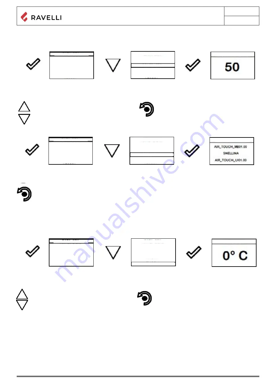
Settings > Contrast
With this function you can change the contrast setting to improve the display of your handheld. The contrast setting to improve the
display of the handheld display.
Use the UP/DOWN keys to change contrast setting and
obtain a better visualisation of the information shown
on the handheld set.
The value can vary from 0 to 100. 50 with respect to
the standard value.
By pressing the following key you will confirm of data
and switch to the page within SETTINGS menu.
Manuale utente PALMARE IDRO TOUCH RADIO
Manuale utente PALMARE IDRO TOUCH RADIO
Pag.30
Pag.31
Vers. 01 del 07/04/15
Vers. 01 del 07/04/15
Below are given the steps for accessing the relative menu starting from Stand-By mode.
Stove State
Press the key
“access menu” to
access the
MENU page
Press the key
“confirm”
to access the
USER page
Press the key
several times
to quickly switch to
Stove STATUS.
To exit the STOVE STATE page and return to Stand-by page, press the button repeatedly.
In this mode you can check the proper operation of the most important parameters of the appliance. Here is a list of real data of the
stove useful for service during inspection.
- Circulator state (ON running)
- Position of 3-way valve DHW (domestic hot water) or HEAT (heating);
- System pressure;
- Stove state;
- Current boiler power;
- Flow read by the flow meter;
- Fume extractor speed;
- Actual flow set;
Settings > Enable thermostat
Press the “enter” key
to access the
SETTINGS
Press the key
“selection” to switch to
ENABLE THERMOSTAT.
Press the key
“confirm”
to access the function
Press the key
“confirm”
to enable the function.
In Stand-By mode, instead of room temperature measured
and settable, appears the line T ON if the room in which
the thermostat is installed has not reached the temperature
requested or the writing T OFF if the temperature in the
room is reached.
Press the key for several
times
to return to
“STAND BY” page
- Temperature read by the handheld unit;
- External thermostat (request ON);
- Flame temperature (combustion chamber);
- Combustion fume exhaust temperature;
- Inlet flow meter temperature;
- Heated flow meter temp.;
- Electronic board temperature;
- Boiler water temperature (SUPPLY);
- Boiler water temperature (optional) - RETURN from the system;
- Boiler DHW temperature;
- Puffer temperature - average warm point;
- Puffer temperature second reading (low temp.).
Below are given the steps for accessing the relative menu starting from Stand-By mode.
Settings
Press the key
“access menu” to
access the
MENU page
Press the key
“confirm”
to access the
USER page
Press the key
“selection” to switch to
second menu page
to the function
SETTINGS.
After following the procedure above step by step, you can set the following functions:
Settings > Contrast
Press the key
“confirm” to
access the
SETUP
SETTINGS
Press the key
“selection” to switch
to the function
CONTRAST.
Press the key
“confirm”
to access the function
Use the UP/DOWN keys to change contrast setting and obtain
a better visualisation of the information shown on the handheld
set.
The value can vary from 0 to 100. 50 with respect to the
standard value.
By pressing the following key you will confirm of data
and switch to the page within SETTINGS menu.
Settings > Season
Press the key
“confirm” to
access the
SETUP
SETTINGS
Press the key
“selection” to switch
to the function
CONTRAST.
Press the key
“confirm”
to access the function
Use the UP/DOWN keys to change the WINTER/
SUMMER season. Function that can be set when
working with DHW puffer (Boiler).
See chap. Evolved hydraulic diagrams
By pressing the following key you will confirm of data
and switch to the page within SETTINGS menu.
Press the “enter” key to
access the
SETTINGS
Press the key
“selection” to switch to
CONTRAST.
Press the key
“confirm”
to access the function
Settings > Firmware version
By pressing the button you will confirm the data and switch to the page within the SETTINGS menu.
MENU
STOVE STATE
STOVE STATE
STOVE STATE
STOVE STATE
USER
ACTIVE PARTS
ACTIVE PARTS
ACTIVE PARTS
ACTIVE PARTS
ACTUAL STATES
PUMP
PRESSURE 1.1 BAR
SHUTDOWN
POWER MOD
HH T …
EXT.T …
FLAME T 340°C
FUME T 120°C
F. EX. T 30°C
C. EX. T 55°C
EL B. T---25°C
T. CALDERA
T.PUFFER H
T.PUFFER L
3-WAY VALVE HEAT
ACTUAL STATES
ACTUAL STATES
ACTUAL STATES
H20 TEMPERATURE
H20 TEMPERATURE
v
H20 TEMPERATURE
TECHNICIAN
STATE TEMPERATURE
STATE TEMPERATURE
STATE TEMPERATURE
STATE TEMPERATURE
USER
USER
POWER SETTING
STOVE STATE
CHRONOTHERMOSTAT
COMFROT CLIMA
SCREW LOADING
SETTING
SET AIR-PELLET
DATE-TIME
DATE-TIME
DATE-TIME
DATE-TIME
DATE-TIME
WINTER
CONTRAST
FIRMWARE
SUMMER
DATE-TIME
ENABLE THERMOSTAT
ENABLE THERMOSTAT
ENABLE EXT. T
ENABLE EXT. T
ENABLE EXT. T
ENABLE EXT. T
ENABLE EXT. T
ENABLE EXT. T
SEASON
SEASON
SEASON
SEASON
SEASON
SEASON
CONTRAST
CONTRAST
CONTRAST
CONTRAST
CONTRAST
CONTRAST
FW VERSION
FW VERSION
FW VERSION
FW VERSION
FW VERSION
FW VERSION
LANGUAGE
LANGUAGE
LANGUAGE
LANGUAGE
LANGUAGE
LANGUAGE
ADJUST
ADJUST
ADJUST
ADJUST
ADJUST
ADJUST
DATE-TIME
ENABLE EXT. T
SEASON
CONTRAST
FW VERSION
LANGUAGE
ADJUST
DATE-TIME
ENABLE EXT. T
SEASON
CONTRAST
FW VERSION
LANGUAGE
ADJUST
MENU
USER
TECHNICIAN
USER
USER
POWER SETTING
STOVE STATE
CHRONOTHERMOSTAT
COMFROT CLIMA
SCREW LOADING
SETTING
SET AIR-PELLET
MANUFACTURER’S
MANUFACTURER’S
Settings > Adjust
The adjust function allows to modify the value read by the room probe inside the handheld computer, increasing or decreasing it by
the set value (offset).
Make this adjustment carefully and only after having checked deviations from the actual room temperature with a reliable instrument!
Manuale utente PALMARE IDRO TOUCH RADIO
Manuale utente PALMARE IDRO TOUCH RADIO
Pag.32
Pag.33
Vers. 01 del 07/04/15
Vers. 01 del 07/04/15
Press the key
“confirm” to
access the
SETUP
SETTINGS
Press the key
“selection” to switch
to the function
VERSION FW.
Press the key
“confirm”
to access the function
To access the next setting, follow the steps given above or simply remove and replace the batteries.
The device resets and prompts you again to select the language you want to set.
Settings > Language
Settings > Adjust
Use the UP/DOWN keys to change the value read by the
room temperature probe installed inside the handheld
set, with respect to a reference value.
The value can vary from -10°C to 10°C.
The standard value is 0°C.
By pressing the following key you will confirm of data
and switch to the page within SETTINGS menu
The stoves equipped with ventilation system can heat the area in which are installed through the heat generated by the window and
the room temperature fan installed inside them.
Below are the messages shown on display when the stove is equipped with ventilation system.
To exit the page and return to Stand-by page, press the button repeatedly.
VENTILATION menu (function only for models in which the same is specified in the dedicate user’s manual)
Control: v
entilation can be set from 0 to AUTO where 0 indicates that the same is disabled, setting from MIN to MAX enables selecting
the heat distribution speed. If set to AUTO, the ventilation follows the power set on the stove.
Press the increase/decrease keys
“increase/decrease”
to change the ventilation.
To exit the page and return to Stand-by page, press the button repeatedly.
The exit key shows the CHRONO menu to set other variables related to the menu functions.
Press the key
“enter” at the end of the
setting, from the following
CHRONO page
The temperature read by the handheld unit controls the modulation of the stove. If you want to adjust the ventilation by
adjusting the stove, set the fan to A mode as shown in the relative chapter.
Press the key
“access menu” to
access the
MENU page
Press the key
“confirm”
to access the
USER page
Press the key
“confirm”
to quickly switch to
VENTILATION.
Press the increase/decrease keys
“increase/decrease”
to change the ventilation.
Pages displayed upon the activation of advanced layouts
By activating a layout different from the standard (layout 0), even if maintaining the same functions of the menu, the “Stand-by” page will
display all connected utilities such as the temperature of the boiler of the puffer.
Below is shown the new display mode and the function of every icon for every layout, to change the various settings.
Layout 1 (DHW heating control)
The following layout can be used when you have a boiler that is not equipped with plate heat exchanger and you intend to buy a puffer
that should be connected to the circuit to produce hot domestic water.
In this type of circuit, room temperature is controlled however by the handheld unit which, being a radio device, acts as a remote
chronothermostat. The boiler is managed by the thermostove through a contact or immersion probe (not supplied) connected directly
to the back of the stove. Below is shown the new “Stand-by” mode.
By setting the SUMMER function, the 3-way valve remains fixed in a single position, enabling the release of heat output
by the stove exclusively inside the boiler. As soon as this condition is reached, the boiler switches to ECO STOP mode.
The operation is the same as for the basic layout except for the fact that in this layout, the boiler exchanges heat directly in the
boiler (priority); when the temperature set is reached, the 3-way valve changes its position and the boiler starts exchanging heat within
the heating circuit. From this moment, the stove is controlled by the radio handheld unit for contolling the room
temperature or via H2 setting (see the operation with layout 0 to find the data on modulation, eco stop etc.).
The 3-way valve is directed again into the boiler when:
- there is a request from the Boiler;
- there is a requested from the flow switch (optional, if connected).
The stove restarts from Eco-stop or Stand by mode according to heating requests or boiler requests.
T°C Boiler
From STAND BY mode, press
the ARROW key UP
to set the
room T°C
and DHW boiler T°C that you
desire.
Boiler water T°C
From STAND BY mode, press
the ARROW key DOWN
to set
the boiler water T°C
that you desire.
Press the key
“V” from STAND BY page
to display the actuale states and
the room temperature
Chrono function
By enabling the chrono function, it is possible to control the ventilation speed for each program as shown in the logic above.
Press the key
“access menu” to
access the
MENU page
Press the key
“confirm”
to access the
USER page
Press the key
several times
to quickly switch to
CRONO-THERMOSTAT.
If the type of system designed requires controlling the 3-way valve (diagram 1 and 3), it is necessary to purchase the
optional kit from the retailer or the authorized Ravelli dealer.
DATE-TIME
DATE-TIME
ENABLE EXT. T
ENABLE EXT. T
SEASON
SEASON
CONTRAST
CONTRAST
FW VERSION
FW VERSION
LANGUAGE
LANGUAGE
ADJUST
ADJUST
ADJUST
MENU
USER
TECHNICIAN
VENTILATION POW.
USER
POWER SETTING
CHRONOTHERMOSTAT
SCREW LOADING
SET AIR-PELLET
MENU
USER
TECHNICIAN
USER
USER
POWER SETTING
POWER SETTING
SET AIR-PELLET
SET AIR-PELLET
CHRONOTHERMOSTAT
CHRONOTHERMOSTAT
SCREW LOADING
SCREW LOADING
CHRONO
CHRONO
ENABLE CHRONO
ENABLE CHRONO
ENABLE CHRONO
ENABLE CHRONO
VENTILATION POW.
SET CHRONO 1
SET CHRONO 1
SET CHRONO 2
SET CHRONO 2
SET CHRONO 3
SET CHRONO 3
SET CHRONO 4
SET CHRONO 4
POWER MOD
PUMP
3-WAY VALVE HEAT
PRESSURE 1.1 BAR
HH T .
21°C
MANUFACTURER’S
MANUFACTURER’S
UP” and “DOWN” buttons The value can vary from
-10°C to 10°C. The standard value is 0°C.
Pressing the following key allows you to confirm the
data and move to the screen within the SETTINGS
menu.
Settings > Language
To access the next setting, follow the steps given above or simply remove and replace the batteries.
The device resets and prompts you again to select the language you want to set.
Settings > Firmware version
By pressing the button you will confirm the data and switch to the page within the SETTINGS menu.
Manuale utente PALMARE IDRO TOUCH RADIO
Manuale utente PALMARE IDRO TOUCH RADIO
Pag.30
Pag.31
Vers. 01 del 07/04/15
Vers. 01 del 07/04/15
Below are given the steps for accessing the relative menu starting from Stand-By mode.
Stove State
Press the key
“access menu” to
access the
MENU page
Press the key
“confirm”
to access the
USER page
Press the key
several times
to quickly switch to
Stove STATUS.
To exit the STOVE STATE page and return to Stand-by page, press the button repeatedly.
In this mode you can check the proper operation of the most important parameters of the appliance. Here is a list of real data of the
stove useful for service during inspection.
- Circulator state (ON running)
- Position of 3-way valve DHW (domestic hot water) or HEAT (heating);
- System pressure;
- Stove state;
- Current boiler power;
- Flow read by the flow meter;
- Fume extractor speed;
- Actual flow set;
Settings > Enable thermostat
Press the “enter” key
to access the
SETTINGS
Press the key
“selection” to switch to
ENABLE THERMOSTAT.
Press the key
“confirm”
to access the function
Press the key
“confirm”
to enable the function.
In Stand-By mode, instead of room temperature measured
and settable, appears the line T ON if the room in which
the thermostat is installed has not reached the temperature
requested or the writing T OFF if the temperature in the
room is reached.
Press the key for several
times
to return to
“STAND BY” page
- Temperature read by the handheld unit;
- External thermostat (request ON);
- Flame temperature (combustion chamber);
- Combustion fume exhaust temperature;
- Inlet flow meter temperature;
- Heated flow meter temp.;
- Electronic board temperature;
- Boiler water temperature (SUPPLY);
- Boiler water temperature (optional) - RETURN from the system;
- Boiler DHW temperature;
- Puffer temperature - average warm point;
- Puffer temperature second reading (low temp.).
Below are given the steps for accessing the relative menu starting from Stand-By mode.
Settings
Press the key
“access menu” to
access the
MENU page
Press the key
“confirm”
to access the
USER page
Press the key
“selection” to switch to
second menu page
to the function
SETTINGS.
After following the procedure above step by step, you can set the following functions:
Settings > Contrast
Press the key
“confirm” to
access the
SETUP
SETTINGS
Press the key
“selection” to switch
to the function
CONTRAST.
Press the key
“confirm”
to access the function
Use the UP/DOWN keys to change contrast setting and obtain
a better visualisation of the information shown on the handheld
set.
The value can vary from 0 to 100. 50 with respect to the
standard value.
By pressing the following key you will confirm of data
and switch to the page within SETTINGS menu.
Settings > Season
Press the key
“confirm” to
access the
SETUP
SETTINGS
Press the key
“selection” to switch
to the function
CONTRAST.
Press the key
“confirm”
to access the function
Use the UP/DOWN keys to change the WINTER/
SUMMER season. Function that can be set when
working with DHW puffer (Boiler).
See chap. Evolved hydraulic diagrams
By pressing the following key you will confirm of data
and switch to the page within SETTINGS menu.
Press the “enter” key to
access the
SETTINGS
Press the key
“selection” to switch to
CONTRAST.
Press the key
“confirm”
to access the function
Settings > Firmware version
By pressing the button you will confirm the data and switch to the page within the SETTINGS menu.
MENU
STOVE STATE
STOVE STATE
STOVE STATE
STOVE STATE
USER
ACTIVE PARTS
ACTIVE PARTS
ACTIVE PARTS
ACTIVE PARTS
ACTUAL STATES
PUMP
PRESSURE 1.1 BAR
SHUTDOWN
POWER MOD
HH T …
EXT.T …
FLAME T 340°C
FUME T 120°C
F. EX. T 30°C
C. EX. T 55°C
EL B. T---25°C
T. CALDERA
T.PUFFER H
T.PUFFER L
3-WAY VALVE HEAT
ACTUAL STATES
ACTUAL STATES
ACTUAL STATES
H20 TEMPERATURE
H20 TEMPERATURE
v
H20 TEMPERATURE
TECHNICIAN
STATE TEMPERATURE
STATE TEMPERATURE
STATE TEMPERATURE
STATE TEMPERATURE
USER
USER
POWER SETTING
STOVE STATE
CHRONOTHERMOSTAT
COMFROT CLIMA
SCREW LOADING
SETTING
SET AIR-PELLET
DATE-TIME
DATE-TIME
DATE-TIME
DATE-TIME
DATE-TIME
WINTER
CONTRAST
FIRMWARE
SUMMER
DATE-TIME
ENABLE THERMOSTAT
ENABLE THERMOSTAT
ENABLE EXT. T
ENABLE EXT. T
ENABLE EXT. T
ENABLE EXT. T
ENABLE EXT. T
ENABLE EXT. T
SEASON
SEASON
SEASON
SEASON
SEASON
SEASON
CONTRAST
CONTRAST
CONTRAST
CONTRAST
CONTRAST
CONTRAST
FW VERSION
FW VERSION
FW VERSION
FW VERSION
FW VERSION
FW VERSION
LANGUAGE
LANGUAGE
LANGUAGE
LANGUAGE
LANGUAGE
LANGUAGE
ADJUST
ADJUST
ADJUST
ADJUST
ADJUST
ADJUST
DATE-TIME
ENABLE EXT. T
SEASON
CONTRAST
FW VERSION
LANGUAGE
ADJUST
DATE-TIME
ENABLE EXT. T
SEASON
CONTRAST
FW VERSION
LANGUAGE
ADJUST
MENU
USER
TECHNICIAN
USER
USER
POWER SETTING
STOVE STATE
CHRONOTHERMOSTAT
COMFROT CLIMA
SCREW LOADING
SETTING
SET AIR-PELLET
MANUFACTURER’S
MANUFACTURER’S
Summary of Contents for Flexi 7
Page 1: ...USE AND MAINTENANCE MANUAL Flexi 7 Flexi 9...
Page 2: ......