background image

17

Manuale utente PALMARE IDRO TOUCH RADIO     

Manuale utente PALMARE IDRO TOUCH RADIO     

Pag.26 

Pag.27 

Vers. 01 del 07/04/15

Vers. 01 del 07/04/15

Operating phases of the appliance

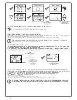
During the work phases, the appliance is aimed at reaching the room/water temperature set by the user;

when one of these conditions is met, the stove switches to MODULE WORK phase, in which fuel consumption is minimised.

Modulation

Should it be necessary to measure the room temperature using an external thermostat (optional), the latter must be 

connected to the dedicated connector to the rear of the stove; therefore, the user will be able to enable temperature reading 

in the dedicated menu “SETTINGS - ENABLE THERMOSTAT”. On display appears the writing TON / TOFF based on 

thermostat request.

CONNECT AN EXTERNAL THERMOSTAT WITH A SIMPLE DRY CONTACT, THEREFORE, NOT POWERED.

  MOREOVER, WE RECOMMEND YOU USE A THERMOSTAT WITH A MINIMUM OFFSET OF 3°C

IF YOU INTEND TO USE THE COMFORT CLIMA FUNCTION.

The activation of this function enables the stove to reduce pellet consumption by activating the modulation phases, after the desired

temperature has been reached. Subsequently, the stove checks that the temperature is maintained steady for a preset time. If this 

condition is met, it automatically switches off, and on display appears the writing ECO. The stove turns on again when the temperature 

drops below the set threshold.

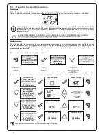
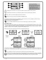
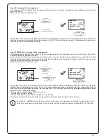
Below are given the steps for accessing the relative menu.

Comfort climate

Press the key

“access menu” to

access the

MENU page

Press the key

“confirm”

to access the

USER page

Press the key “selection” for

several times

to go to the second

page of the USER menu

and select

CLIMATE COMFORT.

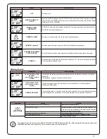
Once you have accessed the Climate Comfort menu, it is possible to operate on the 4 types of settings dedicated to the function:

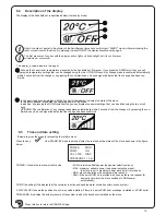
Press the key for several times until the Stand-by page is displayed.

Setting ambient and boiler water temperature:

Set the two values following the indications given in the chapter “Description of the display”

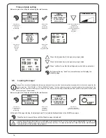
Turning the device on

Keep the key ON/OFF pressed for a few seconds to turn on the stove.

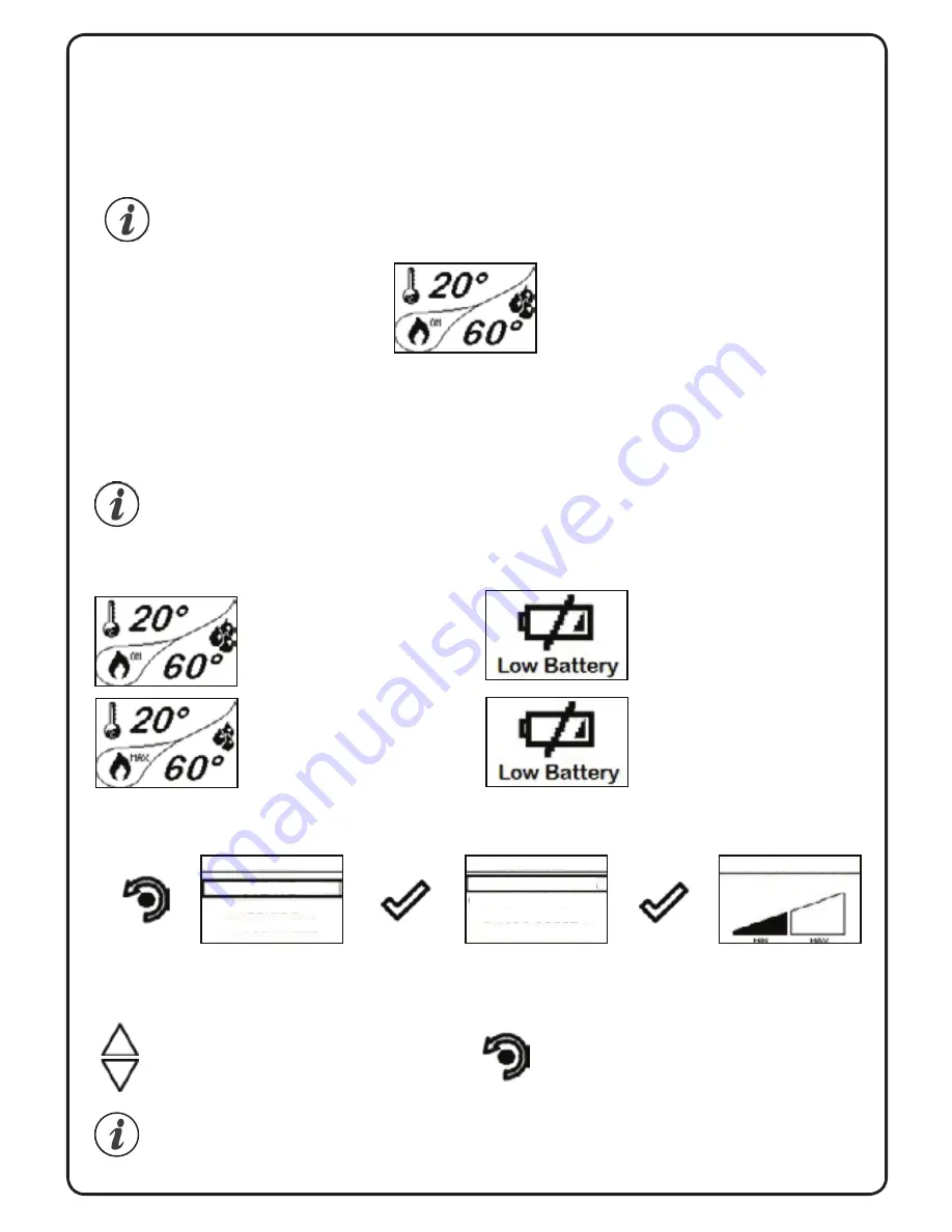
On the display of the handheld set appears the following:

Press and hold the ON/OFF button to turn off the stove and reset any alarms triggered. If the In case the infeed screw operations 

described above have not been executed, the stove may fail to turn on.

  Empty the brazier, reset the alarm and turn the stove on again. If the stove still fails to turn on, make sure the grate is perfectly fixed 

to the support base; also check that there are no deposits that prevent the air to flow correctly and promote the ignition.

If the problem persists, contact the support service.

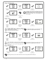
Changing the power of the stove

The message “ADJUST THE RDS SYSTEM” indicates that the initial parameter testing and calibration procedure has 

been completed unsuccessfully. This indication does not block the stove (see section WARNING POP-UP).

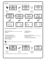
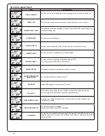
Sequence of ignition phases

SWITCH-ON- initial pellet loading

phase;
WAIT FLAME - flame development

wait  phase;

FLAME PHASE - flame

stabilization and reduction of

combustion inside the brazier;

WORK - operating phase

described in the dedicated chapter;

If the battery is empty, inside the “drop” 

will be displayed a symbol indicating 

the “almost empty” state of the same, 

maintaining the handheld unit functions 

active.

As soon as the level of the battery

prevents the radio communication the 

handheld set displays on full screen the 

picture of empty battery and all device 

functions are locked until the batteries 

are replaced

What happens if the batteries are empty?

For models with automatic cleaning system, the active stove enables a cleaning cycle of the brazier upon ignition and before

IGNITION. In the event of FAILED IGNITION, it is not necessary to remove the unburnt pellet from the inside of the brazier 

before turning on the stove again. As soon as the user restarts the stove, the operating system runs the operation without 

enabling the cleaning device and without reactivating the pellet loading phase.

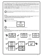
Press the key

“access menu” to

access the

MENU page

Press the key

“confirm”

to access the

USER page

Press the key

“confirm”

to access the

POWER SETTING page

Use the UP/DOWN keys to change the operating power.

By pressing the following key you will confirm the data 

and go back to USER MENU

The power can be selected only when the stove is operating Upon every start-up, the stove operates with maximum power in order to 

ensure greater heat input to the heating system.

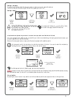
Select the control type

Comfort Clima on t°C

Water or room temperature

using the key

UP/DOWN key

“V” key to confirm the

selection

MENU

USER

MANUFACTURER’S

TECHNICIAN

USER

POWER SETTING

POWER SELECTION

CHRONOTHERMOSTAT

SCREW LOADING

SET AIR-PELLET

MENU

USER

TECHNICIAN

USER

USER

POWER SETTING

STOVE STATE

CHRONOTHERMOSTA

COMFORT CLIMA

COMFORT CLIMA

COMFORT CLIMA

AIR

WATER

COMFORT CLIMA DELTA

COMFORT CLIMA DELTA

SHUTDOWN DELAY

SHUTDOWN DELAY

COMFORT CLIMA

COMFORT CLIMA

SCREW LOADING

SETTINGS

SET AIR-PELLET

ENABLE COMFORT

ENABLE COMFORT

ENABLE COMFORT

ENABLE COMFORT

ENABLE COMFORT

ENABLE COMFORT

COMFORT CONTROL

COMFORT CONTROL

COMFORT CONTROL

COMFORT CONTROL

RESTART DELTA

RESTART DELTA

RESTART DELTA

RESTART DELTA

SHUTDOWN DELAY

SHUTDOWN DELAY

SHUTDOWN DELAY

SHUTDOWN DELAY

MANUFACTURER’S

Manuale utente PALMARE IDRO TOUCH RADIO     

Manuale utente PALMARE IDRO TOUCH RADIO     

Pag.26 

Pag.27 

Vers. 01 del 07/04/15

Vers. 01 del 07/04/15

Operating phases of the appliance

During the work phases, the appliance is aimed at reaching the room/water temperature set by the user;

when one of these conditions is met, the stove switches to MODULE WORK phase, in which fuel consumption is minimised.

Modulation

Should it be necessary to measure the room temperature using an external thermostat (optional), the latter must be 

connected to the dedicated connector to the rear of the stove; therefore, the user will be able to enable temperature reading 

in the dedicated menu “SETTINGS - ENABLE THERMOSTAT”. On display appears the writing TON / TOFF based on 

thermostat request.

CONNECT AN EXTERNAL THERMOSTAT WITH A SIMPLE DRY CONTACT, THEREFORE, NOT POWERED.

  MOREOVER, WE RECOMMEND YOU USE A THERMOSTAT WITH A MINIMUM OFFSET OF 3°C

IF YOU INTEND TO USE THE COMFORT CLIMA FUNCTION.

The activation of this function enables the stove to reduce pellet consumption by activating the modulation phases, after the desired

temperature has been reached. Subsequently, the stove checks that the temperature is maintained steady for a preset time. If this 

condition is met, it automatically switches off, and on display appears the writing ECO. The stove turns on again when the temperature 

drops below the set threshold.

Below are given the steps for accessing the relative menu.

Comfort climate

Press the key

“access menu” to

access the

MENU page

Press the key

“confirm”

to access the

USER page

Press the key “selection” for

several times

to go to the second

page of the USER menu

and select

CLIMATE COMFORT.

Once you have accessed the Climate Comfort menu, it is possible to operate on the 4 types of settings dedicated to the function:

Press the key for several times until the Stand-by page is displayed.

Setting ambient and boiler water temperature:

Set the two values following the indications given in the chapter “Description of the display”

Turning the device on

Keep the key ON/OFF pressed for a few seconds to turn on the stove.

On the display of the handheld set appears the following:

Press and hold the ON/OFF button to turn off the stove and reset any alarms triggered. If the In case the infeed screw operations 

described above have not been executed, the stove may fail to turn on.

  Empty the brazier, reset the alarm and turn the stove on again. If the stove still fails to turn on, make sure the grate is perfectly fixed 

to the support base; also check that there are no deposits that prevent the air to flow correctly and promote the ignition.

If the problem persists, contact the support service.

Changing the power of the stove

The message “ADJUST THE RDS SYSTEM” indicates that the initial parameter testing and calibration procedure has 

been completed unsuccessfully. This indication does not block the stove (see section WARNING POP-UP).

Sequence of ignition phases

SWITCH-ON- initial pellet loading

phase;
WAIT FLAME - flame development

wait  phase;

FLAME PHASE - flame

stabilization and reduction of

combustion inside the brazier;

WORK - operating phase

described in the dedicated chapter;

If the battery is empty, inside the “drop” 

will be displayed a symbol indicating 

the “almost empty” state of the same, 

maintaining the handheld unit functions 

active.

As soon as the level of the battery

prevents the radio communication the 

handheld set displays on full screen the 

picture of empty battery and all device 

functions are locked until the batteries 

are replaced

What happens if the batteries are empty?

For models with automatic cleaning system, the active stove enables a cleaning cycle of the brazier upon ignition and before

IGNITION. In the event of FAILED IGNITION, it is not necessary to remove the unburnt pellet from the inside of the brazier 

before turning on the stove again. As soon as the user restarts the stove, the operating system runs the operation without 

enabling the cleaning device and without reactivating the pellet loading phase.

Press the key

“access menu” to

access the

MENU page

Press the key

“confirm”

to access the

USER page

Press the key

“confirm”

to access the

POWER SETTING page

Use the UP/DOWN keys to change the operating power.

By pressing the following key you will confirm the data 

and go back to USER MENU

The power can be selected only when the stove is operating Upon every start-up, the stove operates with maximum power in order to 

ensure greater heat input to the heating system.

Select the control type

Comfort Clima on t°C

Water or room temperature

using the key

UP/DOWN key

“V” key to confirm the

selection

MENU

USER

MANUFACTURER’S

TECHNICIAN

USER

POWER SETTING

POWER SELECTION

CHRONOTHERMOSTAT

SCREW LOADING

SET AIR-PELLET

MENU

USER

TECHNICIAN

USER

USER

POWER SETTING

STOVE STATE

CHRONOTHERMOSTA

COMFORT CLIMA

COMFORT CLIMA

COMFORT CLIMA

AIR

WATER

COMFORT CLIMA DELTA

COMFORT CLIMA DELTA

SHUTDOWN DELAY

SHUTDOWN DELAY

COMFORT CLIMA

COMFORT CLIMA

SCREW LOADING

SETTINGS

SET AIR-PELLET

ENABLE COMFORT

ENABLE COMFORT

ENABLE COMFORT

ENABLE COMFORT

ENABLE COMFORT

ENABLE COMFORT

COMFORT CONTROL

COMFORT CONTROL

COMFORT CONTROL

COMFORT CONTROL

RESTART DELTA

RESTART DELTA

RESTART DELTA

RESTART DELTA

SHUTDOWN DELAY

SHUTDOWN DELAY

SHUTDOWN DELAY

SHUTDOWN DELAY

MANUFACTURER’S

6.7 

Setting ambient and boiler water temperature:

6.8 

Turning the device on

Summary of Contents for Pompeii

Page 1: ...anual PLEASE READ THIS ENTIRE MANUAL BEFORE INSTALLATION AND USE OF THIS WOOD PELLET BOILER FAILURE TO FOLLOW THESE INSTRUCTIONS COULD RESULT IN PROPERTY DAMAGE BODILY INJURY OR EVEN DEATH Contact your local building or fire official about restrictions and installation requirement in your area ...

Page 2: ...technical programming and individualised air pressure adjustments to ensure it will operate safely and ef ciently and to avoid possible damage to the re or the home Installation of Pompeii the ood Pellet Boiler by a non registered installer will void the warranty and may result in your local authority refusing to approve the ry necessa permits If you require a registered Pellet I Solutions Fire ns...

Page 3: ...tions 6 2 8 Safety Devices 6 2 9 Responsibility 6 2 10 Spare Parts 6 3 What are Wood Pellets 7 4 The Components of the Stove 7 4 1 Pellet Combustion 8 5 Maintenance and Cleaning 9 5 1 Cleaning the surfaces 9 5 2 Automatic cleaning system 9 5 3 Cleaning the Ash Drawer 10 5 4 Cleaning the combustion chamber 10 5 5 Cleaning the Flue 10 5 6 Access to the inspection hatches for cleaning the smoke 11 5 ...

Page 4: ...e Display 15 6 5 Time and Date Settings 15 6 6 Loading the Auger 16 6 7 Setting Ambient and Boiler Water Temp 17 6 8 Turning the Device on 17 6 9 Operating Phases of the Stove 18 6 9 1 d r o c e R e c n a n e t n i a M 7 30 8 Warranty Information 31 9 Proof of Purchase Warranty 33 31 Warranty Coverage Warranty Period Warranty Exclusions 31 32 8 1 8 2 8 3 Alarms 28 ...

Page 5: ... Consumption will vary with the type of fuel used IMPORTANT The above values were found during testing and may vary with the fuel type climate and installation style Pompeii Testing Standard Description Class I IP 20 AS NZS 5078 2007 Appliance AS NZS 4866 2007 Residential Wood Pellet Stove Voltage 220 240 Volt Current 2 92 3 18 Amps Frequency 50Hz Max Power Requirement 550 watts Unit with full hop...

Page 6: ...l l a t s n I r e l a e d Solutions Fire personnel who must give the purchaser a declaration of conformity of the appliance and who will installed It is also necessary to take into consideration all the laws and national regional provincial and local regulations present in the country in which the appliance has been installed In the IMPORTANT The place of installation of the stove must comply with...

Page 7: ...eep 2 Locate the pellet stove in a large and open room that is centrally located in the house This will optimise heat circulation 3 Check clearances to combustibles refer page 37 2 3 Ash The ash content of the fuel and operation of your stove will directly determine the frequency of cleaning The use of high ash fuels may result in the stove needing to be cleaned daily A low ash fuel may allow long...

Page 8: ...ect civil or criminal responsibility due to Poor maintenance Failure to observe the instructions in the manual Use not compliant with the safety instructions Installation that is not compliant with the regulations in force in the country manufacturer Use of spare parts that are not original Exceptional events 2 10 Spare Parts m e h t g n i c a l p e r e r o f e b n r o w e b o t s t n e n o p m o ...

Page 9: ...0 mm Their weight is equal to about 650 kg m Due to the low content of water approx 8 they have a high energy content The standards AS NZS4014 6 de ne the quality of the pellets Do not put the bag of pellets on the cast parts during the loading operations The pellets must be transported and stored in a dry place They swell on contact with any moisture and cannot be used They must always be protect...

Page 10: ... Then adjust set pellet air increasing the air percentage from 0 up to 5 If this doesn t work try increasing the loading quantity of the pellet from 0 up to 5 to reach the flame condition shown in picture 3 If with the adjustments done the flame is not reaching the condition shown in picture 3 contact After Sales Service The combustion is NOT CORRECT the flame is weak and a lot of unburned pellet ...

Page 11: ...i f ep l c f o e h t t o eaning automatic m s i e h t od f o s i h t l e characteristic n i a m sy g n i n a e l c m e t s The Pull l u f e r a c o t e h t r e i z a r b it may still be hot and may damage the equipment used for cleaning t u o e h t r e w a r d m o r f e h t e v o t s d n a e v o m e r e h t h s a n i s u g a l a i c e p s m u u c a v r e n a e l c e b y r e v c x e n i e h t m o o...

Page 12: ...g a drum type vacuum cleaner making sure that the ashes are cold yield and correct functioning 5 5 Cleaning the Flue The will flue require cleaning only once each winter or providing hours 1000 every that the correct only cleaner vacuumn type drum a Use Agent ervice S Solutions Fire Pellet local your with service annual your booking when this for arrange should ou Y used is fuel 5 8 Cleaning the A...

Page 13: ...ody of the pellet stove Clean the inside using a drum type vacuum cleaner 5 7 Frequency of Component Cleaning Parts Frequency Daily 2 3 Days 30 Days Yearly Performed By Burn pot Owner Ash Drawer Owner Glass Owner Flu Technician Door gasket Technician Tubulators scraper Owner Combustion chamber Owner Vacuum Hopper Owner Clean T discharge Technician INSPECTION HATCH GASKET ...

Page 14: ...Pull to clean exchanger tube bundle 12 5 8 How to Clean the Tubulators ...

Page 15: ...RP FRPLQJ LQWR FRQWDFW ZLWK KRW VXUIDFHV Manuale utente PALMARE IDRO TOUCH RADIO Pag 22 Vers 01 del 07 04 15 Wiring RQQHFW WKH SRZHU FRUG WR WKH EDFN RI WKH VWRYH DQG WKHQ WR D ZDOO VRFNHW 7KH 2 VZLWFK LQ WKH JXUH VKRXOG EH VHW WR WR SRZHU WKH VWRYH I YROWDJH LV QRW VXSSOLHG FKHFN WKH VWDWH RI WKH IXVH LQVWDOOHG LQ WKH ER EHORZ WKH VZLWFK IXVH XULQJ WKH SHULRGV RI LQDFWLYLW ZH UHFRPPHQG RX GLVFRQQ...

Page 16: ...JQDO IURP WKH KDQGKHOG VHW SUHVVLQJ WKH HQWHU NH RQ WKH KDQGKHOG VHW WKH FRPSRQHQWV VWDUW FRPPXQLFDWLQJ ZLWK HDFK RWKHU FKHFN VLJQ RQ WKH GLVSOD DFFRPSDQLHG E D VRXQG VLJQDO VKRZV WKDW WKH LQLWLDOL DWLRQ RI WKH KDQGKHOG VHW KDV EHHQ FRPSOHWHG VXFHVVIXOO When you replace the batteries you do not have to run the initialization procedure of the handheld set In this case when on display appears the me...

Page 17: ...m settable power see power selection menu MAX maximum settable power see power selection menu the stove is set to maximum power each time it is turned on MOD stove modulation with set parameters reached SANI if the quick DHW kit is provided as soon as there is a request for domestic hot water the stove switches to DHW power automatically PUMP the writing ON indicates that the circulator is active ...

Page 18: ...N USER POWER SETTING CHRONOTHERMOSTAT SCREW LOADING SCREW LOADING SET AIR PELLET Manuale utente PALMARE IDRO TOUCH RADIO Pag 25 Vers 01 del 07 04 15 Time and date setting Below are given the steps for accessing the relative menu Press the increase key to change every single value Press the increase key to change every single value Press confirm to confirm the settings and switch to the next option...

Page 19: ...NG POWER SELECTION CHRONOTHERMOSTAT SCREW LOADING SET AIR PELLET Manuale utente PALMARE IDRO TOUCH RADIO Pag 26 Vers 01 del 07 04 15 Setting ambient and boiler water temperature Set the two values following the indications given in the chapter Description of the display Turning the device on Keep the key ON OFF pressed for a few seconds to turn on the stove On the display of the handheld set appea...

Page 20: ...ndition is met it automatically switches off and on display appears the writing ECO The stove turns on again when the temperature drops below the set threshold Below are given the steps for accessing the relative menu Comfort climate Press the key access menu to access the MENU page Press the key confirm to access the USER page Press the key selection for several times to go to the second page of ...

Page 21: ...HRONO 2 SET CHRONO 2 SET CHRONO 3 SET CHRONO 3 SET CHRONO 4 SET CHRONO 4 MANUFACTURER S MANUFACTURER S Manuale utente PALMARE IDRO TOUCH RADIO Pag 28 Vers 01 del 07 04 15 The first setting allows you to enable the COMFORT CLIMA function which is aimed at checking that the temperature set for room water is maintained at the set value for a maximum period of X minutes SHUTDOWN DELAY 5 MIN before swi...

Page 22: ...e steps for accessing the relative menu starting from Stand By mode AIR PELLETS setting Press the key access menu to access the MENU page Press the key confirm to access the USER page Press the key several times to quickly switch to SET AIR PELLETS As per the above example you have set a percentage of 2 for PELLETS and 3 for the FLOW an indication that a setting like this is a consequence of the f...

Page 23: ...UPPLY Boiler water temperature optional RETURN from the system Boiler DHW temperature Puffer temperature average warm point Puffer temperature second reading low temp Below are given the steps for accessing the relative menu starting from Stand By mode Settings Press the key access menu to access the MENU page Press the key confirm to access the USER page Press the key selection to switch to secon...

Page 24: ... Season Press the key confirm to access the SETUP SETTINGS Press the key selection to switch to the function CONTRAST Press the key confirm to access the function Use the UP DOWN keys to change the WINTER SUMMER season Function that can be set when working with DHW puffer Boiler See chap Evolved hydraulic diagrams By pressing the following key you will confirm of data and switch to the page within...

Page 25: ...s manual Control ventilation can be set from 0 to AUTO where 0 indicates that the same is disabled setting from MIN to MAX enables selecting the heat distribution speed If set to AUTO the ventilation follows the power set on the stove The temperature read by the handheld unit controls the modulation of the stove If you want to adjust the ventilation by adjusting the stove set the fan to A mode as ...

Page 26: ...bling the release of heat output by the stove exclusively inside the boiler As soon as this condition is reached the boiler switches to ECO STOP mode The operation is the same as for the basic layout except for the fact that in this layout the boiler exchanges heat directly in the boiler priority when the temperature set is reached the 3 way valve changes its position and the boiler starts exchang...

Page 27: ...rough a contact or immersion probe not supplied connected directly to the back of the stove Below is shown the new Stand by mode The operation is the same as for the basic layout except for the fact that in this layout the boiler exchanges heat directly in the boiler priority when the temperature set is reached the 3 way valve changes its position and the boiler starts exchanging heat within the p...

Page 28: ...s at an operating capacity dedicated to DHW flow switch request with DHW kit or DHW boiler MODULATE H2O The desired boiler water set temperature has been reached ROOM TEMPERATURE MODULATION The room temperature set has been reached THE GRATE Brazier cleaning phase is active periodic function ECO STOP With Climate Comfort active the stove switches to automatic switch off mode when the room temperat...

Page 29: ... SOLUTION Set the value back to 0 GENERIC ALARM The stove is in alarm state refer to the troubleshooting chapter ANOMALY general The stove has detected an anomaly refer to the troubleshooting chapter AUTOMATIC CLEANING SYSTEM ACTIVE For models with automatic cleaning system it indicates the operating state of the same STAND BY Forced shutdown state when the boiler water reaches 85 C The stove rest...

Page 30: ...the back of the stove Combustion in the brazier is not optimal due to clogging or obstructions of internal stove ducts inside the stove Switch off the stove clean the brazier and the tube bundle and adjust the combustion setting the Pellet Air values Contacter le Service d Assistance AL 08 DEPRESSION The flue is blocked Check the flue is free and clean The vacuum meter is faulty Check the mains vo...

Page 31: ...e ash pan Cleaning operations of the stove depend on the quality of the pellets used and the frequency of use It may be necessary to carry out these operations on a daily basis EACH ALARM CAUSES THE IMMEDIATE SWITCHING OFF OF THE STOVE PRESS THE SWITCH ON BUTTON TO RESET THE ALARM BEFORE SWITCHING ON THE STOVE MAKE SURE THE SIGNAL HAS BEEN REMOVED AND UNLIKE MODELS EQUIPPED WITH AUTOMATIC CLEANER ...

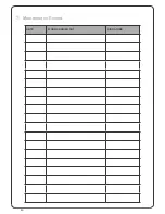
Page 32: ...30 25 Page 16 7 Maintenance Record SIGNATURE WORK CARRIED OUT DATE ...

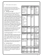
Page 33: ...nal service fees may apply if you are seeking warranty service from a dealer other than the dealer from whom you originally purchased the product Check with your dealer in advance for any costs to you when arranging a warranty call Travel and shipping charges for parts are not covered by this warranty 8 2 Warranty Period Warranty coverage begins at the date of installation In the case of new home ...

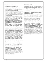
Page 34: ...llet Solution e r i F s approved venting components hearth components or other accessories used in conjunction with the appliance Any part of a pre existing fireplace system Pellet Ravelli i t u l o S on e r i F s r e d n u n o i t a g i l b o s this warranty does not extend to the pellet fires capability to heat the desired space Information is provided to assist the consumer and the dealer in sele...

Page 35: ...ood pellet fire purchase and attach the receipt and any other documents business cards from the retailer that sold you the fire Name of Store where Pellet fire was purchased Date of Purchase Amount Paid Payment Method o Credit Card o EFTPOS o Cash o Other Attach receipt and other documents here ...

Page 36: ... Pellet Stove 38 2 5 Positioning the stove 38 2 6 Location of a power source 38 2 7 Internal Standard Flue Kit 50 39 2 8 External Standard Flue Kit 51 40 2 9 Seismic Restraint 41 2 10 Fixing to Timber Floor Framing 41 2 11 Installation 41 2 12 How to mount the side panels 42 44 2 13 Seismic 2 14 Hydraulic Installation 45 2 15 Examples of Hydraulic Installation Restraint Locations 43 3 Installation...

Page 37: ...s of the product Unit of Measurement Height mm Width mm Depth mm Weight Kg 190 Diameter of smoke exhaust duct mm 80 Min max 1133 476 581 power calorofic kW 3 4 17 2 Min max hourly consump tion of pellets Kg h 1 0 4 0 84 Electrical power absorbed during operation W 240 Supply V Hz 220 50 Tank capacity Kg 23 Space Heating 80 581 81 1133 222 266 50 363 FLOW 3 4 RETURN 3 4 ...

Page 38: ... the fire will shut down completely meaning the likelihood of any hot embers or burning fuel escaping from the combustion chamber is extremely minimal Therefore a 150mm forward projecting protector will be sufficeint Hearth testing of the AS NZS 2918 2001 s n i pecified stove no measured locations exceeded the temperture limits freestanding f o e h t fron u s t rfaces SR 0484 showed that on expose...

Page 39: ...H A E External Flue J J F B I F E Pompeii Pellet Fire Clearance to Combustibles B C A E D G F B F G E Internal Flue Location Dimension mm A B 150 C D E F 0 1 0 G H I J 50 n a 50 0 0 1 50 25 0 1 0 100 Freestanding Clearances from shielded flue 75mm to unlined flue Note AS NZS 2918 requires a minimum of 100mm clearance for any side requiring access Note These are minimum clearances to combustibles A...

Page 40: ...ows air across the top of the unit in the The Pompeii must be installed on a non combustible surface This surface must combustible material also ensure the position of structural elements near the proposed riveted Seismic Restraint Please see Seismic Restraint on page 43 for requirements Warranty To validate warranty following installation a copy of the completed Warranty Producers Statement must ...

Page 41: ...3 6m The visible flue is finished in black and the ceiling plate is white The support angles for securing the liner to the ceiling are not shown Kit is supplied in a carton Heat resistant protector Seismic restraint to be 25mm minimum clearance if lined 75mm minimum clearance if unlined 600mm from roof penetration Note The Davin 50 S B Internal Standard Flue Kit complies with AS NZS 2918 2001 as p...

Page 42: ...enetrating the soffit The overall height of the flue is 3 6m All visible flue has a galvanised finish and can be powdercoated on request Kit is supplied in a carton Note The Davin 51 External Standard Flue Kit complies with AS NZS 2918 2001 as per Applied Research Test Report 05 1185 dated 15 September 2005 All fires must be installed by a qualified installer as per the manufacturer s instructions...

Page 43: ... 11 Installation Pompeii should be installed in a centrally located position within the home This will assist the appliance to perform to the level required As Pompeii heats space by convecting air across the top of the unit the heater should face the area the majority of the area to be heated Pompeii requires a power source to function This is standard mains feed 240v plug if this is unavailable ...

Page 44: ...42 1 2 x 4 2 12 How to mount the side panels ...

Page 45: ...43 38 36 2 13 Seismic Restraint Locations H C T A H N O I T C E P S N I H C T A H N O I T C E P S N I SEISMIC RESTRAINT LOCATION SEISMIC RESTRAINT LOCATION ...

Page 46: ...BILITIES FOR DAMAGES TO PEOPLE OR PROPERTY ARISING FROM MALFUNCTIONS DUE TO FAILURE TO COMPLY WITH THIS WARNING When filling the boiler check that the Jolly valve picture on the left is working properly by venting the system The maximum Loading pressure with COLD water should be of 1 bar In order to ensure proper operation with HOT water the pressure in the stove should be 1 5 bar For installation...

Page 47: ...lves Ambient thermostat Area 1 Area 2 Pellet boiler Distribution heating collectors Radiators Thermometer Manometer Anti condensation valve Non return valve Direct distribution unit Thermostatic distribution unit Radiating panel floor heating Shut off valves Ambient thermostat Expansion vessel Solar pump unit Solar collector Thermostatic mixing valve Potential divider unit Motorized three way valv...

Page 48: ...ffer pipe in tank with DHW Motorized three way valve with spring return Gas boiler Area 1 Area 2 Aqueduct Pellet boiler Distribution heating collectors Radiators Thermometer Manometer Anti condensation valve Non return valve Direct distribution unit Thermostatic distribution unit Radiating panel floor heating Shut off valves Ambient thermostat Expansion vessel Solar pump unit Solar collector Therm...

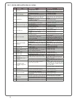
Page 49: ...__________________ Phone ________________________________ Model __________________________ Serial Number ____________________ Date of Purchase __________ dd mm yy Date of Installation _________ dd mm yy Magnehelic at Install _______________ Installer s Signature ________________________________ Name of Installer ________________________________ Address ________________________________ ____________...

Page 50: ...48 38 4 Maintenance Record DATE WORK CARRIED OUT SIGNATURE 40 ...

Page 51: ...operation of my Pellet Fire I understand that warranty conditions require an authorised Pellet Fire Solutions Installer to complete the installation Signed Date Installation Details Pellet Fire Model Serial Number Installation Date Freestanding Flue Kit Internal External Standard Fireplace Insert Flue Kit Insert BIH Installer Details Installers Name Phone Number Passed Inspection Yes No if no why ...

Page 52: ......

Page 53: ......

Reviews: