44
M
L
A
P
e
t
n
e
t
u
e
l
a
u
n
a
M
O
I
D
A
R
H
C
U
O
T
O
R
D
I
E
R
A
M
L
A
P
e
t
n
e
t
u
e
l
a
u
n
a
M
ARE IDRO TOUCH RADIO
Pag.18
Pag.19
Examples of installation of a pellet insert
-
For safety reasons and to ensure proper operation, we
It is recommended to perfectly match the insert with
phase.
Fig.7
Fig.8
Protection from rain
Here you can see the possibility to slide
IT IS STRICTLY FORBIDDEN
TO REMOVE THE STOVE DURING
MAY DISPERSE INTO THE
ENVIROMENT.
Hydraulic installation
Safety devices for closed tank system
According to the standard UNI 10412-2 (2006) in force in Italy, closed systems must be equipped with:
• Safety valve
• Circulator command thermostat
• Acoustic alarm activation thermostat
• Temperature indicator
• Pressure indicator
• Acoustic alarm
• Automatic regulation thermal switch
• Automatic blocking thermal switch (blocking thermostat)
• Circulation system
• Expansion system
• Safety dissipation system built into the generator with thermal safety valve (self-activated), in case the the equipment is not provided
with an automatic temperature regulation system.
The appliances for domestic heating with automatic feeding system must be equipped with a block thermostat for the fuel or with a cooling
circuit provided by the manufacturer of the device, activated by a thermal safety valve that ensures that the compliant temperature threhold
set is not exceeded. Connection between the power supply unit and the valve must be without shut-offs. Pressure upstream of the cooling
circuit must at least be 1.5 bar.
Installation advice
After placing the boiler and installing all fume exhaust pipes, you can connect the hydraulic system. It is recommended to connect the
boiler to the system by means of ball valves or gate valves, in order to enable easy detachment, if needed. Before connection we strongly
recommend you carry out a thorough cleaning of the system. We recommend that you connect the vent of the safety valve through a
special pipe in order to prevent damage in case of overpressure or increase in temperature.
PLUMBING MUST ALWAYS BE CARRIED OUT BY QUALIFIED PERSONNEL, ABLE TO CARRY OUT A STATE-OF-THE-
ART INSTALLATION IN COMPLIANCE WITH THE LAWS IN FORCE IN THE COUNTRY OF INSTALLATION, AFTER HAVING
READ THE NEXT CHAPTER. RAVELLI DENIES ALL LIABILITIES FOR DAMAGES TO PEOPLE OR PROPERTY ARISING
FROM MALFUNCTIONS DUE TO FAILURE TO COMPLY WITH THIS WARNING
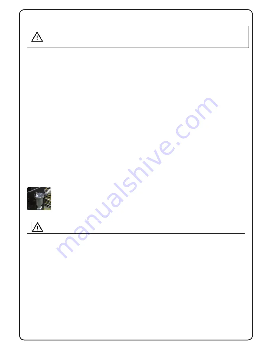
When
fi
lling the boiler, check that the Jolly valve (picture on the left) is working properly by venting the system. The
maximum Loading pressure with COLD water should be of 1 bar.
In order to ensure proper operation with HOT water, the pressure in the stove should be 1.5 bar.
For installation of an additional expansion tank, remember that normally 1 litre of expansion tank compensates 10 litres of
the system and at least two litres are always dedicated to the water inside the stove.
FILLING MUST BE CARRIED OUT USING A “T“ JOINT PLACED ON THE HEATING SUPPLY, LOADING TO A MAXIMUM
OF 1 BAR WITH COLD WATER PERIODICALLY CHECK ON THE CONTROL CONSOLES THE PRESSURE IN THE
STOVE, AND KEEP IT STEADY AT 1 BAR.
Correctly connect the stove to the hydraulic system, bringing pressure of the system to 0.8 or max 1 bar when the stove has not yet been
switched on (in the event the system is not a closed tank system, but has an open tank, it is necessary to change the setting on the menu,
which is reserved to authorised technician).
Now proceed to bleed the hydraulic system using the valve assembled on the boiler or using the valves assembled on the radiators. This
operation can be carried out multiple times, even after activation of the boiler since, from the time the temperature of the water starts to
increase, the air bubbles move towards the high part of the boiler. Once you have completed this operation, close the feeding valve.
While bleeding the boiler, ensure the electrical parts near the valve are not wet!
In the event this occurs, do not turn on the boiler, but proceed to dry the electronic board using a hairdryer.
THE HYDRAULIC CONNECTION PROVIDES EXCLUSIVELY THE PRESENCE OF OUR CIRCULATOR INTO THE
STOVE AT SYSTEM RETURN LINE. REFER TO THE DEDICATED SECTION TO SEE HOW TO CONNECT EVERY
SINGLE MODEL.
Pellet Fire Solutions, along with Ravelli, only recommend the use of a closed loop system when installing the Pompeii Pellet Boiler.
2.14 Hydraulic installation
Summary of Contents for Pompeii
Page 14: ...Pull to clean exchanger tube bundle 12 5 8 How to Clean the Tubulators ...
Page 32: ...30 25 Page 16 7 Maintenance Record SIGNATURE WORK CARRIED OUT DATE ...
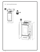
Page 44: ...42 1 2 x 4 2 12 How to mount the side panels ...
Page 50: ...48 38 4 Maintenance Record DATE WORK CARRIED OUT SIGNATURE 40 ...
Page 52: ......
Page 53: ......

