


C
HAPTER
5
42
AutoBoom® XRT Installation Manual for Case IH Patriot 3XX0/44X0 and Trident 5550 (MY 2017-19)
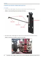
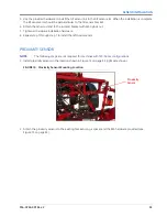
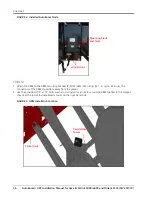
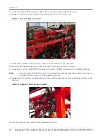
FIGURE 10. Machine’s Tilt Sensor
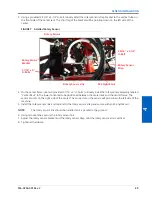
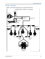
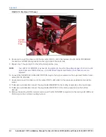
8. Route and connect the other end of the tee cable (P/N 115-0235-104) between the RH LEVEL POS SENSOR
connection and OEM cabling located on the right side of the center rack.
9. Repeat step 7 though step 8 for the left cylinder position plug.
NOTE:
The LEVEL POS SENSORS may need to be adjusted to be within the voltage range of 4.4 to 4.6 volts
when booms are tilted all the way up. AutoFold will require recalibration once these sensors are
adjusted.
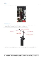
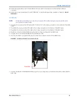
10. Connect the CENTER RACK ANGULAR POSITION plug to the 4-pin receptacle on the Superseal Position Sensor
cable (P/N 115-010-069).
11. Route and connect the other end of the cable (P/N 115-0235-069) to the previously installed center rotation
sensor.
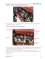
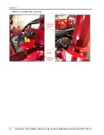
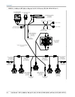
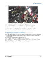
12. If dampers were installed, connect the plug labeled DAMPER 1 to the mating receptacle on the top damper.
13. If dampers were installed, connect the plug labeled DAMPER 2 to the mating receptacle on the bottom
damper.
14. Remove the existing CAN Terminator and connect the ISO CAN/PWR receptacles to the mating AUX PWR and
CAN plugs on the machine’s existing harness.
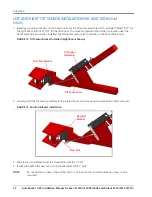
Cylinder
Position
Plug


