C
HAPTER
4
32
AutoBoom® XRT Installation Manual for Case IH Patriot 3XX0/44X0 and Trident 5550 (MY 2017-19)
LEFT AND RIGHT TILT SENSOR INSTALLATION (90’ AND 100’ BOOM
ONLY)
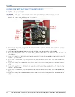
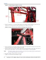
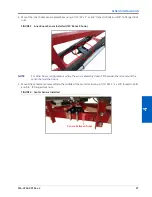
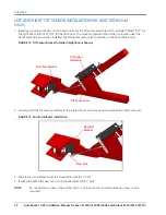
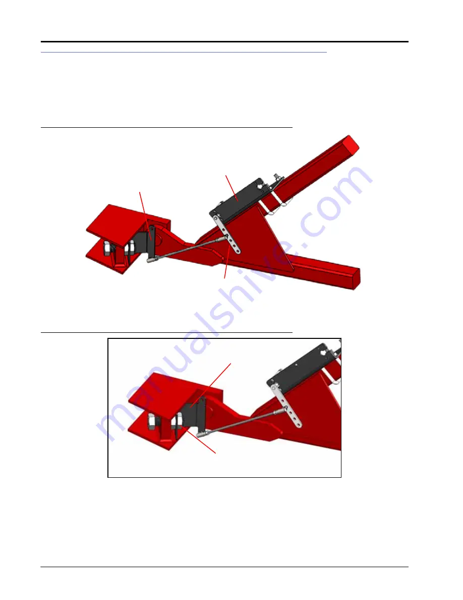
1. Identify a mounting location on the boom frame for the tilt sensor assembly which is labeled “RIGHT TILT” for
the right boom and “LEFT TILT” for the left boom. The mounting position should be in a location near the
boom pivot point and, when installed, the tilt bracket sensor arm should be on the back of the boom.
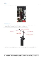
FIGURE 12. Tilt Sensor Bracket Installed (Right Boom Shown)
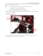
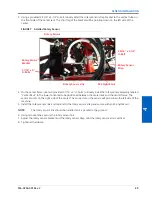
2. Loosely install the tilt sensor assembly to the angled boom structure using two provided U-bolts and nuts.
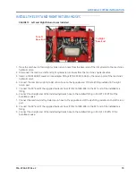
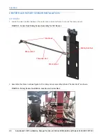
FIGURE 13. Rod End Bracket Installation
3. Slide the rod end bracket over the threaded end of the 1” bolt.
4. Install and tighten the new nut on the threaded end of the 1” bolt.
NOTE:
Do not tighten or loosen the existing bolt or nut to which the rod end bracket and new nut are
mounted.
Tilt Sensor
Assembly
Tilt Sensor Arm
Rod End Bracket
Rod End
Bracket
New Nut

