background image


CHAPTER 

SYSTEM TROUBLESHOOTING 

________________________________________________________________________ 
 

The CAN AccuBoom Node P/N 063-0172-316 has additional features to 
allow the user to diagnose the AccuBoom system. The CAN AccuBoom 
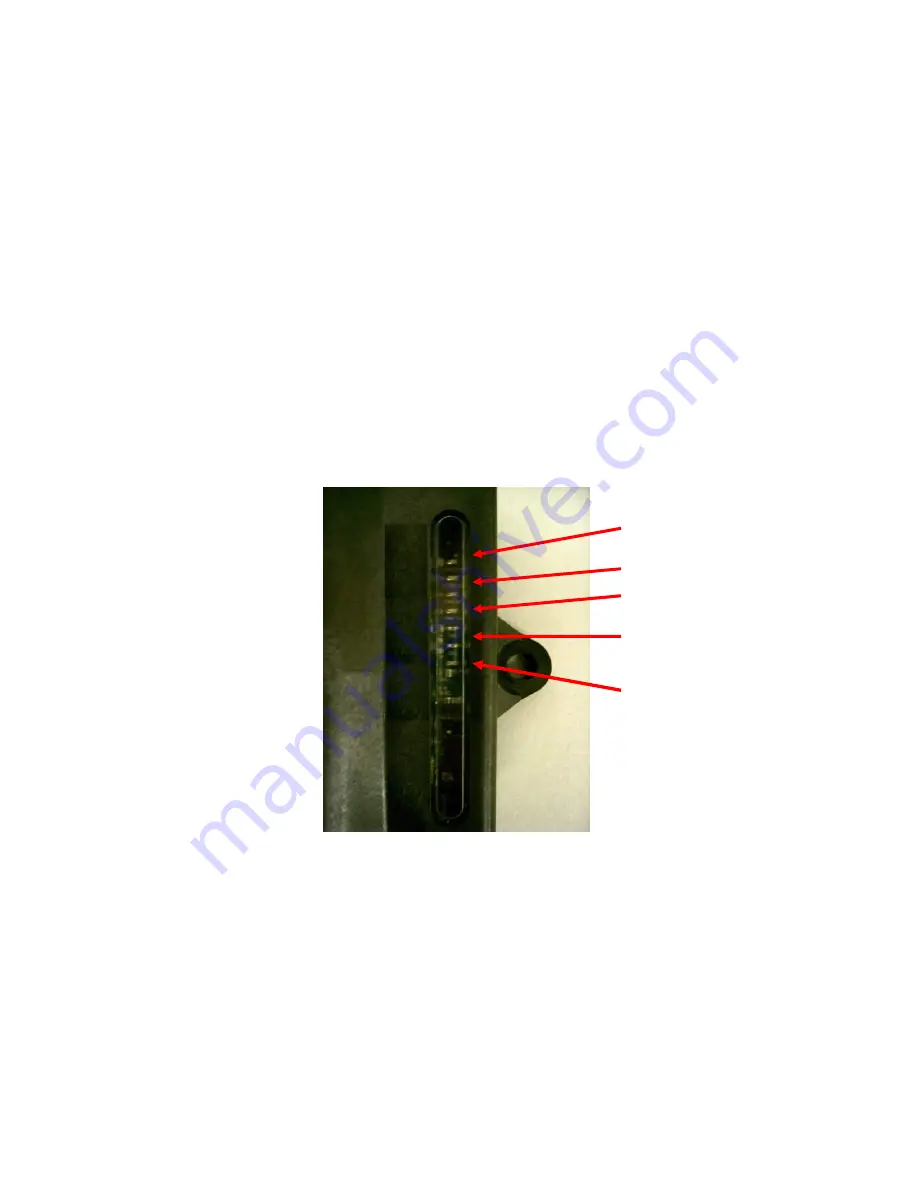
node has a plastic window in the case that allows the user to view green 
diagnostic lights. The picture below shows the positioning and function of 
each of the LED lights.  

Logic Power 

High Current 
Power (HC) 

Micro 1 Hz 

CAN Rx 

CAN Tx 

Manual #016-0171-081  Rev. B  07/08 


Logic Power:

 Lit when 12VDC logic power is available at the node. 


Micro 1 Hz:

 Flashes at 1 Hz interval when processor is active. 


CAN Rx:

 Flashes when CAN messages are being received. 


CAN Tx:

 Flashes when CAN messages are being transmitted. 


High Current Power:

 Lit when High Current Power is applied to the 

node. 

11 

Summary of Contents for Case SPX 3150

Page 1: ...Case SPX 3150 3185 3200 Sprayer with Raven SCS 460 Console AccuBoom Installation Manual P N 016 0171 081 Rev B 01 16 Copyright 2009 2016 ...

Page 2: ......

Page 3: ...ee your Console Operation Manual for instructions on setting up the software and using the AccuBoom system Important All boom switches must remain in the OFF position while AccuBoom control is in operation COMPONENTS NEEDED CAN AccuBoom Control Node P N 063 0172 316 CASE3150 3185 3200 CAN AccuBoom Cable P N 115 1001 011 6 CAN Tee Cable 115 0171 326 AccuBoom installation Manual CASE SPX3150 3185 32...

Page 4: ...Manual 016 0171 081 Rev B 07 08 Notes 2 ...

Page 5: ...___________________________________ Use the following procedure to properly install the AccuBoom system on a CASE SPX3150 3185 3200 sprayer 1 Open the access door located on the left side of the cab 2 Locate the boom control cable located toward the rear of the cable compartment 3 ...

Page 6: ...nnections Important There may be two sets of 6 pin connectors Be sure you have located the connectors coming from the boom switches 4 Plug the mating connectors from the CAN AccuBoom cable P N 115 1001 011 to the corresponding connectors previously disconnected 4 ...

Page 7: ...6 to the CAN connection on the CAN AccuBoom cable P N 115 1001 011 8 If using a Viper or Viper Pro console connected serially to the SCS 460 connect the orange wire from the AccuBoom harness 115 1001 011 to the Master Apply Switch so that the orange wire is supplied power when the Master Apply switch is in the ON position If you are not using a Viper or Viper Pro connected serially to the SCS 460 ...

Page 8: ...Manual 016 0171 081 Rev B 07 08 6 ...

Page 9: ...m exists on the machine refer to Chapter 3 and use on of the terminators contained in the CAN Tee With Power kit P N 117 0159 923 10 Connect the CAN system a Connect the single end of the CAN cable P N 115 0171 326 to the CAN bus or to the CAN PWR Tee system installed in Chapter 3 11 Connect power and ground a Wire the red power wire to a clean source of switched 12 volt power b Connect the white ...

Page 10: ...Manual 016 0171 081 Rev B 07 08 Notes 8 ...

Page 11: ...his kit contains the CAN Cable Adapter Tee With Power P N 115 0171 368 and two 2 CANBus Terminators P N 063 0172 369 To install a Raven CAN system 1 Connect CAN Tee to power and ground a Locate a convenient source of power and ground near the control system b Connect the red wire of the CAN Cable Adapter Tee With Power P N 115 0171 368 to a source of clean 12 volt power c Connect the white wire fr...

Page 12: ... to one connector on the Can Cable Adapter Tee With Power P N 115 0171 368 CAN Terminator b Connect the second connector on the CAN Cable Adapter Tee With Power P N 115 0171 368 to the CAN connector on the Envizio or Viper interface cable The CAN bus system is now installed and CAN nodes may be connected to it 10 ...

Page 13: ...ew green diagnostic lights The picture below shows the positioning and function of each of the LED lights Logic Power High Current Power HC Micro 1 Hz CAN Rx CAN Tx Manual 016 0171 081 Rev B 07 08 Logic Power Lit when 12VDC logic power is available at the node Micro 1 Hz Flashes at 1 Hz interval when processor is active CAN Rx Flashes when CAN messages are being received CAN Tx Flashes when CAN me...

Page 14: ...Manual 016 0171 081 Rev B 07 08 Notes 12 ...

Page 15: ...e Coverage Period How Can I Get Service What Will Raven Industries Do What is not Covered by this Warranty Bring the defective part and proof of purchase to your Raven Dealer If your Dealer agrees with the warranty claim the Dealer will send the part and proof of purchase to their distributor or to Raven Industries for final approval Upon confirmation of the warranty claim Raven Industries will at...

Reviews: