Chapter 3
10
Challenger MT 7XXC and MT 8XXC Series SmarTrax Installation Manual
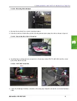
FIGURE 5.
Foot Switched Installed
6.
Mount the foot switch to the floor of the cab using screws or double-sided tape (not included in the
installation kit).
Note:
The foot switch should be mounted in a location that allows the front of the pedal to be fully
pressed without interference.
7.
Connect the foot switch to the node cable.
Steering-Only Systems
On systems using the 115-4001-085 chassis cable, leave the jumper plug on the connector labeled “To
SmarTrax Node.” Install the 115-4001-089 harness cable between the 115-4001-085 chassis cable and the
console cable (P/N 115-0171-926 or 115-4001-066).
Steering with Additional Nodes
On systems using multiple Raven nodes, install the 115-4001-089 harness cable between the chassis cable
(P/N 115-0171-915) and the console cable (P/N 115-0171-926).
Summary of Contents for Challenger MT 7XXC Series
Page 4: ...Table of Contents ii Challenger MT 7XXC and MT 8XXC Series SmarTrax Installation Manuall ...
Page 18: ...Chapter 4 16 Challenger MT 7XXC and MT 8XXC Series SmarTrax Installation Manual ...
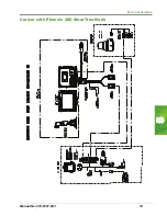
Page 21: ...5 Manual No 016 0197 003 19 Wiring Schematics Cruizer with Phoenix 200 SmarTrax Node ...
Page 23: ...5 Manual No 016 0197 003 21 Wiring Schematics Cruizer with Helix Antenna SmarTrax Node ...
Page 24: ...Chapter 5 22 Challenger MT 7XXC and MT 8XXC Series SmarTrax Installation Manual ...
Page 26: ...Index 24 Challenger MT 7XXC and MT 8XXC Series SmarTrax Installation Manual ...


