background image

30

PLAN OVERVIEW

The plan overview screen displays the full plan. Each plan consists of field regions, 

lines, and offsets specific to that field. From this page, the user can add, edit, or 

remove regions. Any changes to the regions will be reflected in the plan overview 

screen.
1. Press the Add button to the right of the desired baseline. The first baseline 

selected will generate the guidance line for the main or center field region. 

Additional baselines will be added in headland regions.

FIGURE 14. Create Regions

2. Press the Edit 

 button to modify a region.

3. Adjust the desired settings.

FIGURE 15. Region Settings

Summary of Contents for CR Series

Page 1: ...1 016 0171 664 Rev F 6 2019 E33023 Copyright 2019 CRX Operation Guide...

Page 2: ...n Industries shall not be held responsible for any modifications or repairs made outside our facilities nor damages resulting from inadequate maintenance of this system As with all wireless and satell...

Page 3: ...GFF 23 Start a Job 24 Start or Resume a Job 24 Start a New Job in a New field 25 Operation Planning 26 Pre Planning 27 Planning 29 Run Screen Overview 32 Run Screen Overview 32 Widgets 34 WIDGET OPTI...

Page 4: ...File 53 Delete a File 53 Import Maps Guidance Lines and Feature Unlocks 54 Load A Prescription Map 56 Eject the USB 58 Software and Hardware Updates 59 Software 59 Downloading a CRX Update to USB 60 I...

Page 5: ...bright easy to use touchscreen interface and ISO Universal Terminal UT and Task Controller TC capabilities making these field computers a flexible plug and play option for building an affordable syst...

Page 6: ...lightweight field computer with a simplified widget concept FIGURE 1 CR7 Field Computer Touch Screen Integrated Light Bar Ethernet Port 1 RAM Mount I O Cable Connection Power Button USB Port Power an...

Page 7: ...s feature Dustproof design Anti reflective though screen for optimal visibility Clear and easy to use Integrated Wi Fi module for easy remote support FIGURE 2 CR12 Field Computer Touch Screen Ethernet...

Page 8: ...850 NITS Computing 8 GB Storage 1 GB RAM 852 MHz Quad Core Processor 30 GB Internal Storage 1 GB RAM Quad Core Cortex A9 Processor Power 7 to 16 VDC Input 850 mA Typical Supply Power Fuse 5 Amp MINI...

Page 9: ...ironment Even when powered down the field computer will draw a small amount of power from the vehicle battery If the machine will not be in operation for an extended period of time e g more than a cou...

Page 10: ...ortal ravenprecision com INITIAL SET UP When starting the system for the first time a setup wizard will walk you through a setup process and if desired allow you to quickly begin creating guidance lin...

Page 11: ...ss Previous to return to the previous screen 3 Select the desired time zone from the drop down NOTE Time zones are based on an offset from Coordinated Universal Time UTC Ex Los Angeles is UTC 08 00 Ne...

Page 12: ...screen will display 9 Enter the desired grower name in the Name the Default Grower field 10 Press Next The First Run Setup Configure Machine Configuration screen will be displayed NOTE A Machine Conf...

Page 13: ...License Agreement prompt will be displayed 4 Review the information in the End User License Agreement and select OK The Warning prompt will be displayed 5 Read and acknowledge the information on the W...

Page 14: ...with starting a job See Run Screen Overview section on page 32 for additional information on using tools and features during an in field operation STATUS BAR The status bar provides a quick reference...

Page 15: ...ot operation manual for additional information on Slingshot functionality Remote Support Disabled Remote support session is not active Refer to the Remote Support on page 46 for additional information...

Page 16: ...e Refer to Software and Hardware Updates on page 59 for additional information on updates USB Transfer CRX is transferring files from the connected USB drive Outdoor Sensor Outdoor Sensor is communica...

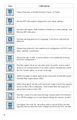
Page 17: ...l menus TABLE 3 Settings Screens Icon Information Add menu options to the Shortcut Bar for quick access to frequently used settings and features Base Stations allows for the creation and configuration...

Page 18: ...d as the input for master switch status of connected nodes If no other options are selected select the On Screen option to record coverage Select this page to adjust prescription map Look Ahead settin...

Page 19: ...L Sensitivity and the Line Acquire speed configure all SmarTrax settings and run SmarTrax calibration If there is a software update available it can be installed on this page using either Slingshot Li...

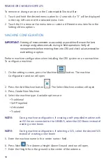
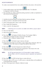
Page 20: ...iguration when installing the CRX system on a new machine To configure a machine 1 On the settings screen press the Machine button The machine Configuration window will open 2 Press the Add Machine bu...

Page 21: ...ked machine select if the antenna is in front of or behind the track center 14 Press Next For Articulated Tractors enter The Distance Rear Axle to Pivot NOTE This allows CRX to calculate the correct p...

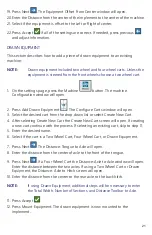
Page 22: ...will open The Guidance Width is automatically assigned the same value as the Total Width 11 If desired enter a different Guidance Width 12 Press Next The Section Layout window will open 13 Review the...

Page 23: ...he drop down list or select Create New Cart 4 After selecting Create New Cart the Create New Cart screen will open If creating a new cart continue with the process If selecting an existing cart skip t...

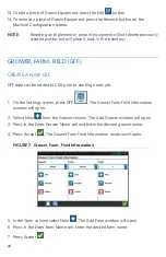
Page 24: ...GFF GFF data can be added to CRX prior to starting a new job 1 On the Settings screen press GFF The Grower Farm Field Information window will open 2 Select New from the Grower column The Add Grower wi...

Page 25: ...formation window will open 2 Select the desired Grower Farm and or Field from the drop down options RENAME A GROWER FARM OR FIELD 1 Ensure the desired GFF is visible in the drop down 2 Select Rename T...

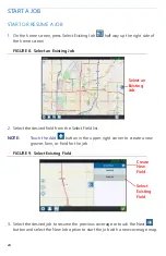
Page 26: ...d field from the Select Field list NOTE Touch the Add button in the upper right corner to create a new grower farm or field for the job FIGURE 9 Select Existing Field 3 Select the desired job to resum...

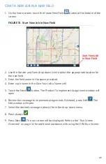
Page 27: ...provided 4 Enter a job name in the Give Your Job a Name cell 5 Touch the Next button The Product To Implement Assignment window will open 6 Review the coverage to implement assignments If desired pre...

Page 28: ...an existing field boundary Operation planning consists of two parts Pre planning allows the user to adjust field boundary and lines that are created based on the boundary Planning allows the user to c...

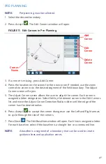
Page 29: ...orner Each corner is assigned a letter designation Select Edit by the desired corner in the Edit Corners list and move the Adjust Corner Detection Radius slider until the edge of the corner has the de...

Page 30: ...baselines will affect the field boundary used when running the plan 8 To change a baseline from a contoured line to a straight line select the desired radial button next to the baseline name in the Ed...

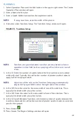
Page 31: ...line or extra wheel width wills start Typically this will be the number of planter swaths it takes to apply half of the sprayer width NOTE Adjust any of the cells on the Tramlines Setup page automatic...

Page 32: ...hanges to the regions will be reflected in the plan overview screen 1 Press the Add button to the right of the desired baseline The first baseline selected will generate the guidance line for the main...

Page 33: ...onal Tramlines using the side panel 12 Select an existing guidance line and select the Add button to create a new tramline NOTE If necessary select the remove button to delete a tramline from the oper...

Page 34: ...widget to access the settings Any settings updated within the job will be saved and applied to the plan RUN SCREEN OVERVIEW The image below is an example of a run screen This section provides basic i...

Page 35: ...nce line Last Pass Create a Last Pass line with this widget Pivot Create an pivot guidance line with this widget Scouting Object Provides information on existing scouting features and creating scout f...

Page 36: ...ys the machine elevation Applied Area Provides options for showing the applied area s Course Over Ground Provides settings for configuring the settings for the GPS course Distance Off Guidance Line Di...
Page 37: ...on the Run screen 3 Touch the Accept button in the lower right corner to return to the run screen and resume normal in field operation and application controls SmarTrax Status Add the SmarTrax widget...

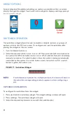
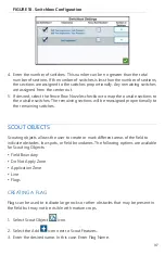
Page 38: ...ton to turn press the left most button to turn on or off all switches that are not already manually turned on If a switch button is blue the switch is being automatically controlled by the system If a...

Page 39: ...aining sections will be reassigned proportionally to the remaining switches SCOUT OBJECTS Scouting objects allows the user to create or mark different areas of the field to indicate obstacles low spot...

Page 40: ...n area where product should always be applied They are generally used inside a do not apply zone 1 Select Scout Object icon 2 Select the Add icon next to Scout Features 3 Select the desired task 4 Sel...

Page 41: ...tomatically option to allow CRX to automatically close the field boundary when the position nears the spot where the field boundary recording started 9 After selecting End Recording press Accept to co...

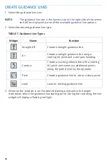
Page 42: ...ing point and in the proper orientation select the guidance line starting point During the recording the line widget will display a flashing red light Widget Name Function Straight AB Create a straigh...

Page 43: ...guidance line icon along the right side of the screen 7 Select the Edit next to the newly created line The Edit Guidance Line window will open 8 Enter a name for the guidance line 9 Press Accept If de...

Page 44: ...should be set to a lower value On Off Look Ahead monitors the GPS position and coverage map while considering the look ahead times to begin controlling sections on or off before the section crosses sp...

Page 45: ...st those colors 11 Press Accept CRX SETTINGS MENU DISPLAY To access display settings 1 Press Display on the CRX Settings page The Display Settings window will open 2 The default settings for the displ...

Page 46: ...3 00 4 Select either an AM PM clock or a 24 hour clock 5 Use the check box options to set the desired display units for Speed Area Weight Volume Pressure and Temperature 6 Touch the Accept button to s...

Page 47: ...port tabs to view and edit GPS information for those ports In some cases Port may be referred to as COM FIGURE 22 GPS Port Configuration NOTE Port A is not configurable 4 Press the INFORMATION tab to...

Page 48: ...ormation To enable remote support NOTE Remote support on CRX can only be performed via Slingshot 1 Press Remote Support on the CRX Settings screen The Remote Support page will open 2 Select the Enable...

Page 49: ...put wire to act as a master switch AccuBoom Select this option if there is a wired switch on the AccuBoom cabling orange wire to act as a master switch Steering Select this option if you want the Smar...

Page 50: ...r manual steering 5 The default setting for Path Deviation Sensitivity is Fine To adjust the Path Deviation Sensitivity select the desired radial button While adjusting the sensitivity note that the l...

Page 51: ...connect to that Wi Fi hotspot If an invalid password is entered a notification will open saying the password was invalid NOTE If desired for future Wi Fi connections to this hotspot select Connect Aut...

Page 52: ...Internet source To create a Personal Hotspot 1 Press Hotspot 2 Select the Enable Wi Fi Hotspot checkbox The SSID number displayed will the be network name The Password is the password to connect to t...

Page 53: ...red USB drive from the Send To dropdown 5 Select Screen captures 6 If desired enter a Comment about the screen shot VIEWING SCREEN SHOTS After the screen shot has been exported to a USB drive view the...

Page 54: ...device or on the installed USB memory stick Backup Backup files can be saved on the CRX or moved to a USB port These files can include backups of machine configurations GFF information and jobs Guidan...

Page 55: ...copy the file or Cancel to stop copying the file 6 Press Accept after selecting the desired file s DELETE A FILE 1 Press File Manager on the CRX Settings page The File Management window will open 2 S...

Page 56: ...ress File Manager on the CRX Settings page The File Management window will open 2 Select USB from the left most drop down FIGURE 26 File Management All Files 3 Navigate to and select the desired file...

Page 57: ...opy Files The files will copy to the CRX 6 To verify unlocks have transferred successfully navigate to the Features tab in the System Update field The downloaded unlocks should now display with an ope...

Page 58: ...prescription maps 2 Insert the USB drive into the CRX 3 Select File Manager on the settings page 4 Select the desired USB drive from the left most drop down FIGURE 30 File Management All Files 5 Sele...

Page 59: ...select Edit beside the desired prescription map FIGURE 32 Coverage to Implement Assignment 10 Select the desired prescription map from the No Rx Map drop down 11 Select Rate from the Select Rate Colum...

Page 60: ...escription map will be visible on the run screen FIGURE 34 Run Screen Prescription Map EJECT THE USB If a USB stick was installed press Eject USB button to properly save the information on the USB sti...

Page 61: ...nload button will change to Install Press Install to install the software update 4 If desired press the Features tab to access the desired unlock The following options are available GPS Unlocks Unlock...

Page 62: ...1 On a computer enter http portal ravenprecision com into the address bar 2 Press Enter 3 Click Product Documentation 4 Click CRX 5 Navigate to the dropdown 6 Select the desired Software NOTE If desir...

Page 63: ...on select the information icon To see the if there is a newer version compare the Current Version to the Latest Version FIGURE 36 Hardware Updates 4 To install the update press anywhere on the device...

Page 64: ...Operation Manual IMPLEMENT STEERING SYSTEM INFORMATION The Implement Steering Information page provides options for adjusting sensitivity performing diagnostics and general Implement Steering informa...

Page 65: ...temporary unlock expires the feature will be available using the activation package Contact a local Raven dealer for additional assistance with temporary unlocks or feature activation To activate a t...

Page 66: ...ocks the files are loaded to the CRX with a USB drive To install a permanent unlock on the CRX 1 Locate the file sent to you from the Raven dealer 2 On a computer create a folder named Raven 3 Transfe...

Page 67: ...turn off the system press the System Shutdown button or press the power button on the back of the CRX A Confirm Shutdown window will open 2 Press Accept to turn off the system or Cancel to return to...

Page 68: ...up crb crb Cruizer Flags WorkOrders Jobs Job Dir jdf zone inj fld fcp com Cruizer Flags Coverage_Maps Job Dir logs scout dat Diagnostics dbg ePro Line ePro WorkOrders GuidanceLines ab Field Raven GFF...

Page 69: ...shx dbf prj shp shx dbf prj Raven GFF Grower Name Farm Name Field Name RxMaps shp shx dbf prj ROS Line Raven GFF Grower Name Farm Name Field Name scoutRoot ScoutGroup id Scouted Object sct sct Street...

Page 70: ...the original owner and is non transferable HOW CAN I GET SERVICE Bring the defective part and proof of purchase to your Raven dealer If the dealer approves the warranty claim the dealer will process t...

Page 71: ...sible for damage to any associated equipment or products and will not be liable for loss of profit labor or other damages The obligation of this warranty is in lieu of all other warranties expressed o...

Page 72: ...not have a serial tag the kit it came in must be registered instead WHERE CAN I REGISTER MY PRODUCT FOR THE EXTENDED WARRANTY To register go online to www ravenhelp com and select Product Registration...

Page 73: ...nd the claim itself Raven Industries will at our discretion repair or replace the defective product and pay for the standard return freight regardless of the inbound shipping method Expedited freight...

Reviews: