PAGE 16/36 | Installation manual | 016-8000-014EN | Rev. A1
Raven Industries Inc.
STEERING SYSTEM INSTALLATION | CRX + SC1 | RAVEN EUROPE GENERIC
1.3.2
HYDRAULIC INSTALLATION LOAD SENSE
The manifold should be connected between the hoses
leading from the steering orbitrol to the steering
cylinder(s). To do so, the hoses must be disconnected,
preferably on an existing connection between a pipe
line and a hose.
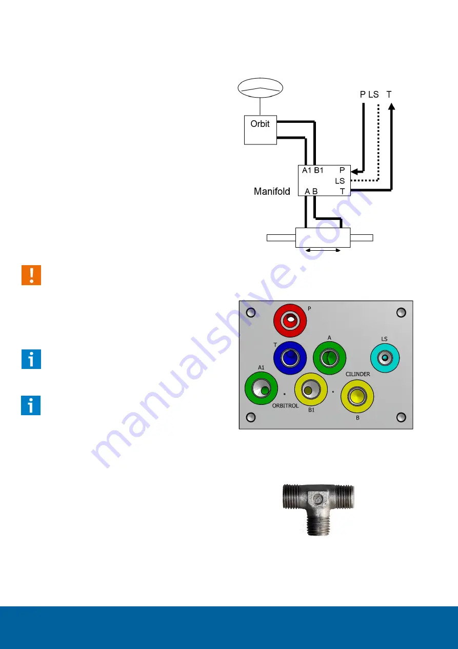
Connect the hoses from the steering orbitrol to A1
and B1 on the manifold. Connect the hoses to the
steering cylinders to A and B on the manifold (Figure
5Figure 6 and Figure 7).
Connect the pressure line, return line and the LS line of
the hydraulic pump to the P, T and LS of the manifold.
When needed refer to the hydraulic drawing of the
tractor to find the correct connections on the tractor.
Caution!:
If there are separate hydraulic systems with
separate oil tanks on the tractor, the manifold
must be connected to the system in which the
steering orbitrol and steering cylinder are
included in.
Hint!:
Mark the lines twice with 'A' and 'B', before
disconnecting them.
Hint!
:
Raven Europe can supplies hose kits for different
types of tractors. Please inquire about the
possibilities.
1.3.3
CONNECTING THE SHUTTLE VALVE
A shuttle valve should be installed in the load sense
line. See Figure 8 for proper mounting and orientation
of the shuttle valve. This way, when in rest, the ball
inside the shuttle valve floats inside the valve, which
will benefit the response for the load sense signal. In
addition, it is important that the shuttle valve is
installed as close to the pump as possible.
Steering Cylinder(s)
Signal from
manifold
Signal from
other users
Signal to LS-
pump
FIGURE 6 LOAD SENSE CONNECTING CIRCUIT
FIGURE 7 CONNECTIONS FOR THE HYDRAULIC
LOAD SENSE MANIFOLD
FIGURE 8 TOP VIEW OF SHUTTLE VALVE FOR
MOUNTING IN THE LOAD SENSE LINE.


