STEERING SYSTEM INSTALLATION | CRX + SC1 | RAVEN EUROPE GENERIC
PAGE 23/36 | Installation manual | 016-8000-014EN | Rev. A1
1.
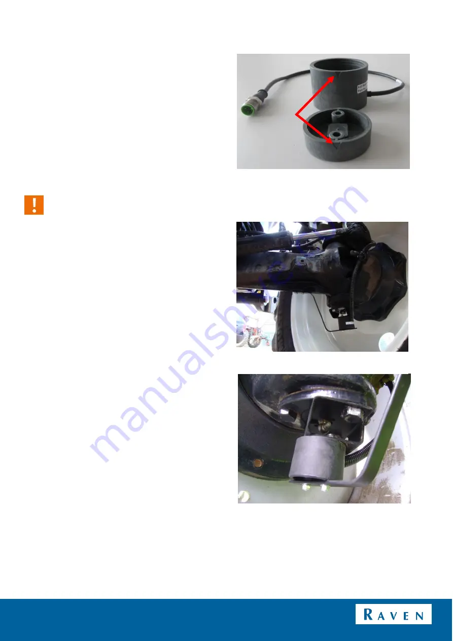
If there is a grease nipple at the bottom of the
stub axle (stub axle with triangle), then a
special U-shaped bracket is to be used for the
wheel angle sensor
housing (Figure 19 and
2.
It is recommended to assemble the sensor
housing on the bottom side of the axle stub.
Install the sensor housing with the wire
pointing backwards.
Caution!:
Sensor housing should always be mounted
above the disk to prevent the accumulation of
dirt.
3.
Mount the sensor housing with the M5X16
bolts (allen bolt, countersunk head).
Countersink the drill holes in the wheel angle
sensor mounting bracket beforehand, so the
heads of the M5 bolts are fully countersunk in
the mounting bracket when tightened (Figure
19) To prevent damage to the inside of the the
sensor housing, make sure the M5 bolts are
not too long.
4.
The connecting cable can be provided with a
protective sleeve for longer life. Feed the cable
via the stub axle and direct it over the top
(stub axle/pivot point) of the front axle so that
the wire is not pinched or constricted.
FIGURE 18 TRIANGULAR MARKINGS ON THE 12V
WHEEL SENSOR
FIGURE 19 STEERING ANGLE SENSOR ON NEW
HOLLAND.
FIGURE 20 STUB AXLE WITH GREASE NIPPLE.


