PAGE 24/36 | Installation manual | 016-8000-014EN | Rev. A1
Raven Industries Inc.
STEERING SYSTEM INSTALLATION | CRX + SC1 | RAVEN EUROPE GENERIC
1.3.11
MOUNTING THE SENSOR DISC
1.
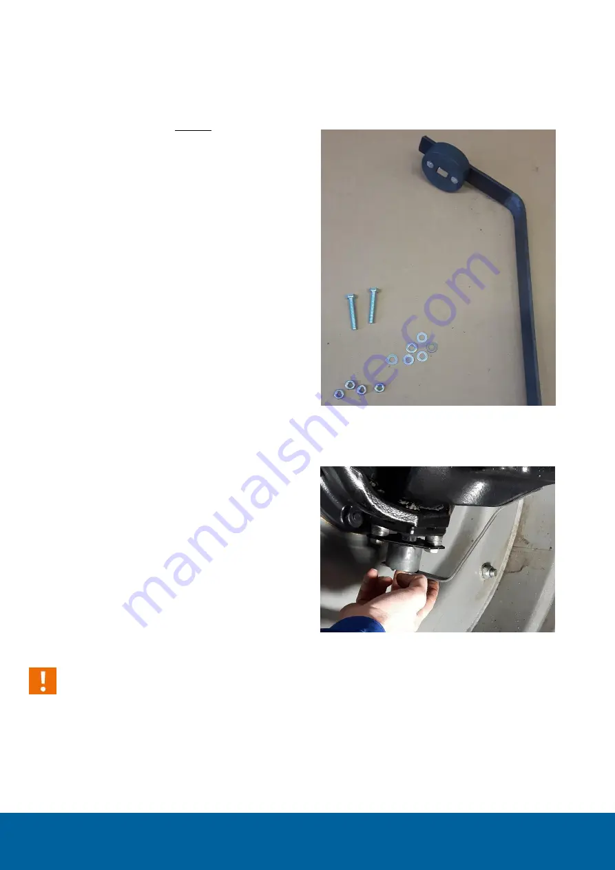
Mount the sensor disc without spacers on the
provided 20x3 strip (Figure 21).
2.
Mount the sensor disc in the sensor housing
and mark where the first bend should be made
(about 10 cm from the beginning). The first
bend should be as close as possible to the
sensor disc and be positioned as tight as
possible against the stub axle housing to
prevent damage by crops or soil (Figure 21 and
Figure 22). The most extreme wheel position is
usually the tightest position of the strip. Do not
bend the strip too sharply.
3.
Mark the position of the second bend in the
strip until the sensor disc fits nice and flat in
the sensor housing. On the other side, the strip
must rest just underneath and against the front
axle. The strip should rest on the sensor
housing. Cut the strip to the correct length.
4.
The wheel angle sensor strip should now be
mounted to the bottom of the front axle
(Figure 22). Mark the location of the holes on
the strip and drill two 5 mm holes in the strip
at approximately 30 mm apart.
5.
Hold the strip with disc in the correct position
and drill the first hole in the front axle with a 5
mm drill bit (about 10-15 mm deep). Drill into
the thickest part of the front axle. Not too
deep!
Caution!:
Ensure that the hole does not wear out when
drilling (drill clean and straight). When drilling,
ensure that the strip is under tension when
positioned against the sensor housing to prevent
the strip from vibrating.
FIGURE 21 DISC ON THE STRIP WITHOUT SPACERS
FIGURE 22 STRIP WITH SECOND BEND AND
SHORTENED


