


STEERING SYSTEM INSTALLATION | CRX + RS1 | RAVEN EUROPE GENERIC
PAGE 21/35 | Installation manual | 016-8000-028EN | Rev. A1
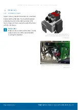
1.2.10
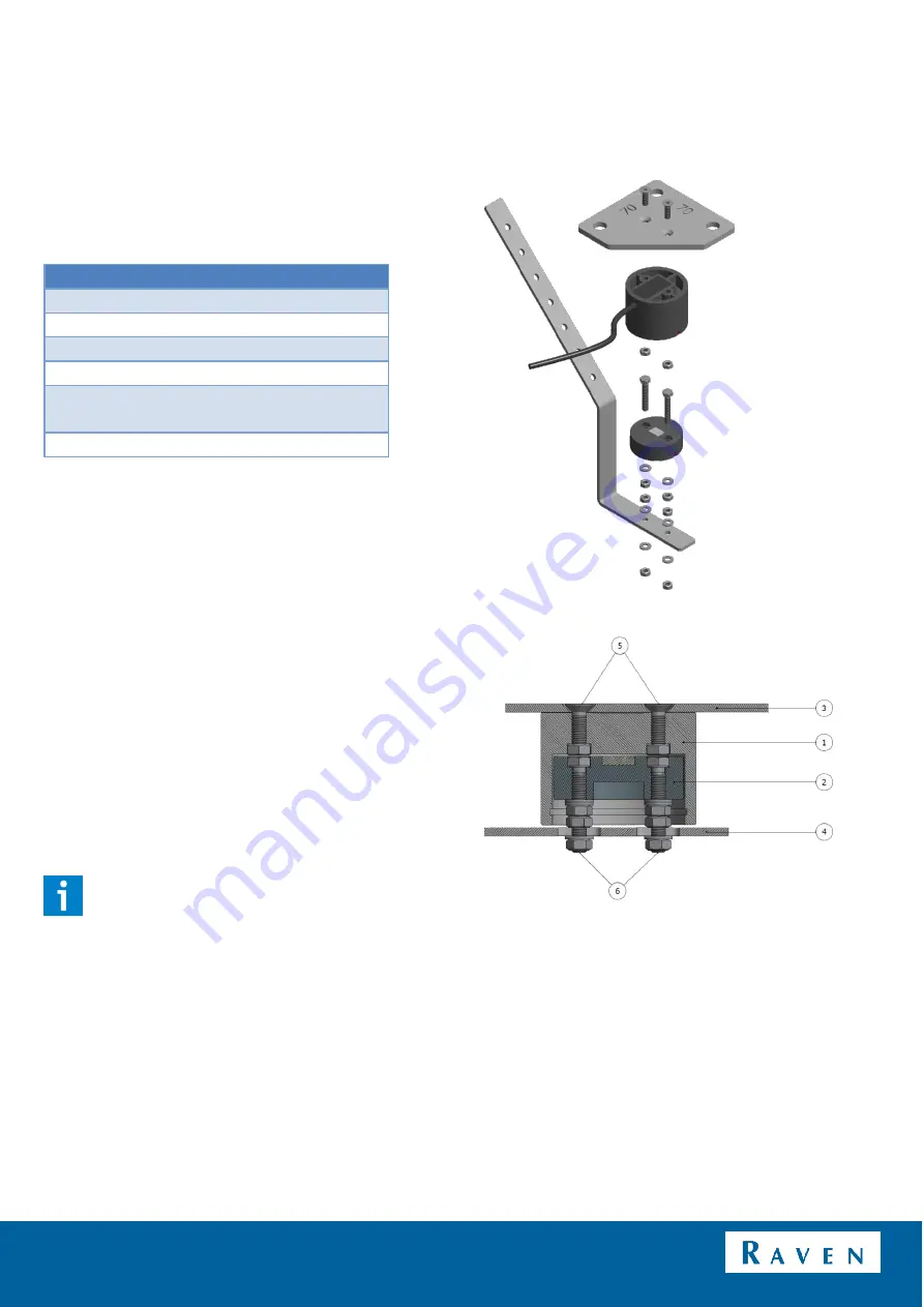
MOUNTING THE WHEEL ANGLE SENSOR
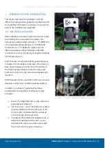
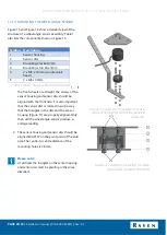
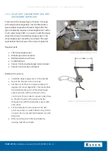
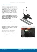
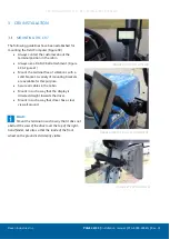
Figure 15 and Figure 16 show a detailed view of the
structure of a wheel angle sensor assembly. Table 1
also lists the components shown in Figure 15.
Symbol Description
1
Sensor housing
2
Sensor disc
3
Mounting bracket 3mm
4
Mounting strip 20x 3mm
5
2 x M5 x 16mm (countersunk
head)
6
2 x M5 x 30mm
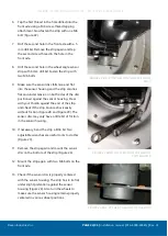
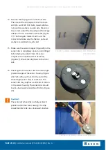
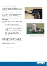
1.
If
the front wheels are straight, the screws of the
sensor housing and sensor disc should be
aligned with the front axle. It is also important
that the sensor disc is rotated in such a way
that the triangles in the disc and the sensor
housing (Figure 17) are properly aligned. Only
then will the wheel angle sensor produce a
voltage reading.
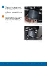
2.
The sensor housing and sensor disc should be
aligned EXACTLY on the pivot point of the stub
axle. The centre-to-centre distance of the
mounting holes is 28 mm.
Please note!:
At all times the triangles on the sensor housing
and sensor disc must be pointing in the same
direction!
TABLE 1 WHEEL ANGLE SENSOR COMPONENTS.
FIGURE 15 SCHEMATIC OVERVIEW OF WHEEL
ANGLE SENSOR WITH MOUNTING BRACKET
AND STRIP.
FIGURE 16 SCHEMATIC DRAWING OF WHEEL
ANGLE SENSOR WHEN MOUNTED.