P/N 016-0171-675 Rev. A
11
INSTALLATION
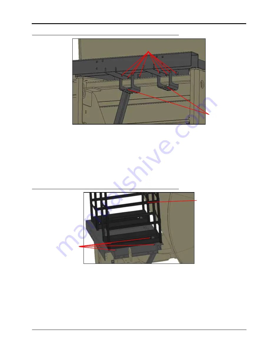
FIGURE 7. Lower Tank Support Strap
2. Secure with 1/2” hardware. Do not tighten at this time.
TANK FRAME INSTALLATION
Refer to the tank Table 1 on page 17 for tank mounting configuration details.
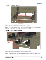
1. Using the provided 1/2” hardware in the four hardware locations, install the tank frames (P/N 116-0159-759) for
all available tanks (for up to three tanks).
FIGURE 8. Tank Frame Installation
FOURTH TANK (OPTIONAL) INSTALLATION
1. Mount the fourth tank frame (P/N 116-0159-825) to the upper tank base frame using the supplied 1/2”
hardware.
Lower Tank
Support Straps
Tank Support
Strap Hardware
Tank Frame
Hardware
Locations
Tank Frame
Summary of Contents for ICD Sidekick Pro
Page 48: ...CHAPTER 5 44 ICD Sidekick Pro Injection for Case Trident Installation Manual ...
Page 57: ...P N 016 0171 675 Rev A 53 SYSTEM DIAGRAMS ...
Page 58: ...CHAPTER 6 54 ICD Sidekick Pro Injection for Case Trident Installation Manual ...
Page 60: ...INDEX 56 ICD Sidekick Pro Injection for Case Trident Installation Manual ...


