3
Hydraulic System Installation: Mount the Steering Valve
13
HYDRAULIC SYSTEM INSTALLATION
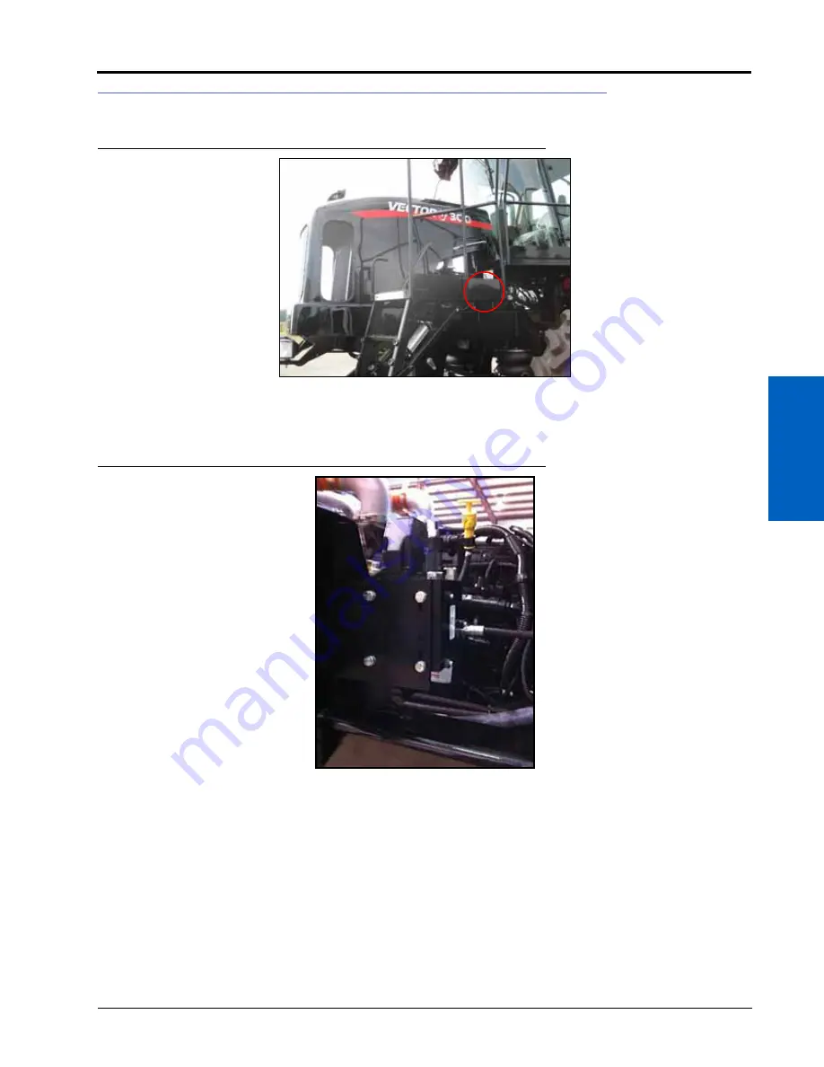
MOUNT THE STEERING VALVE
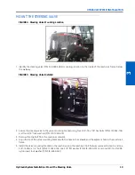
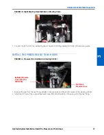
FIGURE 2. Steering Valve Mounting Location
1. Identify the steering valve (P/N 334-0003-088) mounting location on the inside of the machine’s frame, below
the walkway.
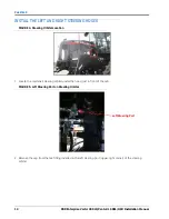
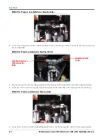
FIGURE 3. Steering Valve Installed
2. Secure the steering valve to the valve mounting bracket using four 5/16”-18 x 7/8” hex bolts (P/N 311-0052-104)
and four 5/16” lock washers (P/N 313-1000-019).
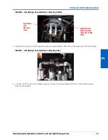
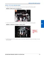
3. Remove the top bolt from the machine’s catwalk.
4. Align the lip of the valve mounting bracket with the hole in the catwalk and the adjacent hole in the machine’s
frame.
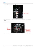
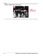
5. Install the valve mounting bracket on the machine using the machine’s bolt that was removed in step 2 and one
3/8”-16 UNC x 1-4” bolt (P/N 311-0054-106, one 3/8” flat washer (P/N 313-2300-013), and one 3/8”-16 UNC 3B
nylon insert lock washer (P/N 312-4000-061).
Summary of Contents for RS1/HDU
Page 4: ...Table of Contents ii RBR Enterprise Vector 300 LS Venturi LS RS1 HDU Installation Manual...
Page 8: ...CHAPTER 1 4 RBR Enterprise Vector 300 LS Venturi LS RS1 HDU Installation Manual...
Page 12: ...CHAPTER 2 8 RBR Enterprise Vector 300 LS Venturi LS RS1 HDU Installation Manual...
Page 13: ...2 Introduction Updates 9 INTRODUCTION...
Page 14: ...CHAPTER 2 10 RBR Enterprise Vector 300 LS Venturi LS RS1 HDU Installation Manual...
Page 26: ...CHAPTER 3 22 RBR Enterprise Vector 300 LS Venturi LS RS1 HDU Installation Manual...
Page 30: ...CHAPTER 4 26 RBR Enterprise Vector 300 LS Venturi LS RS1 HDU Installation Manual...
Page 45: ...Cab Component Installation System Diagrams 41 CAB COMPONENT INSTALLATION SYSTEM DIAGRAMS...
Page 46: ...CHAPTER 5 42 RBR Enterprise Vector 300 LS Venturi LS RS1 HDU Installation Manual...
Page 51: ...APPENDIX A 44 RBR Enterprise Vector 300 LS Venturi LS RS1 HDU Installation Manual...
Page 53: ...Index 46 RBR Enterprise Vector 300 LS Venturi LS RS1 HDU Installation Manual...

