C
HAPTER
5
36
RBR Enterprise Vector 300 LS/Venturi LS RS1/HDU Installation Manual
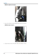
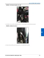
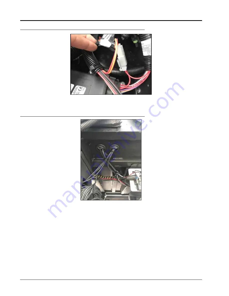
FIGURE 19. 2-Pin Connector on the HDU Valve Cable
4. Route the HDU valve cable outside of the cab using the circular hole in the cab floor.
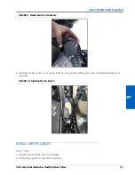
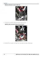
FIGURE 20. Feeding HDU Cable out of Cab
5. Route the HDU valve cable to the steering valve.
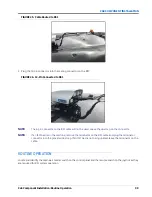
6. Plug the 3-pin connector into the pressure transducer and the 4-pin connector into the valve.
Summary of Contents for RS1/HDU
Page 4: ...Table of Contents ii RBR Enterprise Vector 300 LS Venturi LS RS1 HDU Installation Manual...
Page 8: ...CHAPTER 1 4 RBR Enterprise Vector 300 LS Venturi LS RS1 HDU Installation Manual...
Page 12: ...CHAPTER 2 8 RBR Enterprise Vector 300 LS Venturi LS RS1 HDU Installation Manual...
Page 13: ...2 Introduction Updates 9 INTRODUCTION...
Page 14: ...CHAPTER 2 10 RBR Enterprise Vector 300 LS Venturi LS RS1 HDU Installation Manual...
Page 26: ...CHAPTER 3 22 RBR Enterprise Vector 300 LS Venturi LS RS1 HDU Installation Manual...
Page 30: ...CHAPTER 4 26 RBR Enterprise Vector 300 LS Venturi LS RS1 HDU Installation Manual...
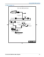
Page 45: ...Cab Component Installation System Diagrams 41 CAB COMPONENT INSTALLATION SYSTEM DIAGRAMS...
Page 46: ...CHAPTER 5 42 RBR Enterprise Vector 300 LS Venturi LS RS1 HDU Installation Manual...
Page 51: ...APPENDIX A 44 RBR Enterprise Vector 300 LS Venturi LS RS1 HDU Installation Manual...
Page 53: ...Index 46 RBR Enterprise Vector 300 LS Venturi LS RS1 HDU Installation Manual...


