CHAPTER
4
Wheel Angle Sensor Installation: Assemble the WAS
23
CHAPTER 4
WHEEL ANGLE SENSOR
INSTALLATION
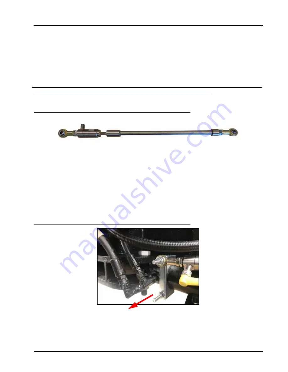
ASSEMBLE THE WAS
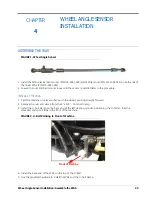
FIGURE 1. Wheel Angle Sensor
1. Install the M10 universal ball mounts (P/N 103-0001-029) and M29 jam nuts (P/N 312-1002-035) on both ends of
the linear WAS (P/N 416-0001-052).
2. Leaven the nuts and ball mounts loose until the sensor is installed later in the procedure.
INSTALL THE WAS
1. Park the machine on a level surface with the wheels pointing straight forward.
2. Remove the nuts and clamp from the 3” x 3/8” - 16 U-bolt clamp.
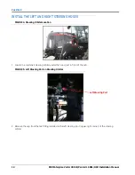
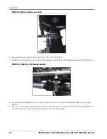
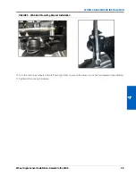
3. Install the U-bolt clamp on the base end of the left steering cylinder, positioning the U-bolt so that the
threaded ends point toward the front of the machine.
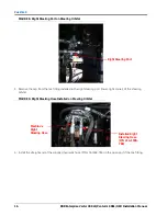
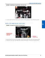
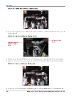
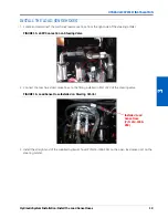
FIGURE 2. U-Bolt Pointing to Front of Machine
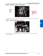
4. Install the base end of the WAS on the top of the U-Bolt.
5. Use the provided hardware to install the WAS and the U-bolt clamp.
Front of Machine
Summary of Contents for RS1/HDU
Page 4: ...Table of Contents ii RBR Enterprise Vector 300 LS Venturi LS RS1 HDU Installation Manual...
Page 8: ...CHAPTER 1 4 RBR Enterprise Vector 300 LS Venturi LS RS1 HDU Installation Manual...
Page 12: ...CHAPTER 2 8 RBR Enterprise Vector 300 LS Venturi LS RS1 HDU Installation Manual...
Page 13: ...2 Introduction Updates 9 INTRODUCTION...
Page 14: ...CHAPTER 2 10 RBR Enterprise Vector 300 LS Venturi LS RS1 HDU Installation Manual...
Page 26: ...CHAPTER 3 22 RBR Enterprise Vector 300 LS Venturi LS RS1 HDU Installation Manual...
Page 30: ...CHAPTER 4 26 RBR Enterprise Vector 300 LS Venturi LS RS1 HDU Installation Manual...
Page 45: ...Cab Component Installation System Diagrams 41 CAB COMPONENT INSTALLATION SYSTEM DIAGRAMS...
Page 46: ...CHAPTER 5 42 RBR Enterprise Vector 300 LS Venturi LS RS1 HDU Installation Manual...
Page 51: ...APPENDIX A 44 RBR Enterprise Vector 300 LS Venturi LS RS1 HDU Installation Manual...
Page 53: ...Index 46 RBR Enterprise Vector 300 LS Venturi LS RS1 HDU Installation Manual...


