Manual No. 016-0171-079 Rev F
11
ACCUBOOM INSTALLATION
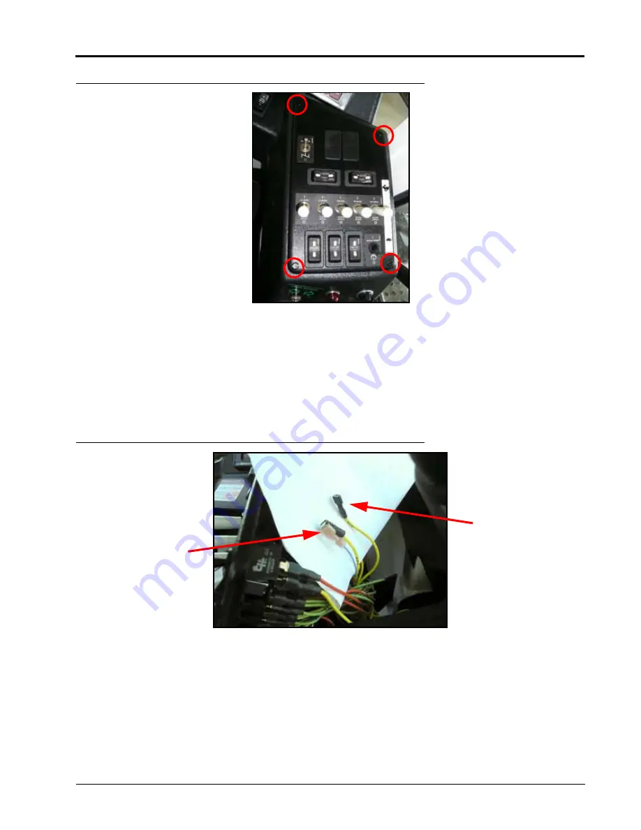
FIGURE 6. Boom Switch Console
1. Remove the four screws (shown in the figure above) used to secure the cover on the boom switch console.
2. Carefully remove the cover of the boom switch console.
3. Locate the parallel positive and negative wires located at the bottom of boom switch 1.
NOTE:
The positive boom switch wire has an adapter that allows two wires to be connected to the switch
connector (parallel). The connector the positive boom switch wire is connected to triggers the driver
when in manual mode.
FIGURE 7. Boom Switch Wires Disconnected
4. Disconnect the parallel positive and negative boom switch wires from the bottom of the switch.
IMPORTANT:
When connecting the boom valve connections, refer to Table 1 below if the machine has three boom
sections, and Table 2 for five boom sections.
Negative Boom
Switch Wire
Parallel Positive
Boom Switch
Wire and
Console Wire
Summary of Contents for SCS 460
Page 2: ......
Page 4: ...Table of Contents ii SpraCoupe 3000 4000 with SCS 460 Console AccuBoom Installation Manual ...
Page 22: ...CHAPTER 3 18 SpraCoupe 3000 4000 with SCS 460 Console AccuBoom Installation Manual ...
Page 24: ...CHAPTER 4 20 SpraCoupe 3000 4000 with SCS 460 Console AccuBoom Installation Manual ...
Page 26: ...CHAPTER 5 22 SpraCoupe 3000 4000 with SCS 460 Console AccuBoom Installation Manual ...
Page 28: ...Index 24 SpraCoupe 3000 4000 with SCS 460 Console AccuBoom Installation Manual ...


