Chapter 3
12
John Deere 8X60 and 8X70 Series SmarTrax™ MD Installation Manual
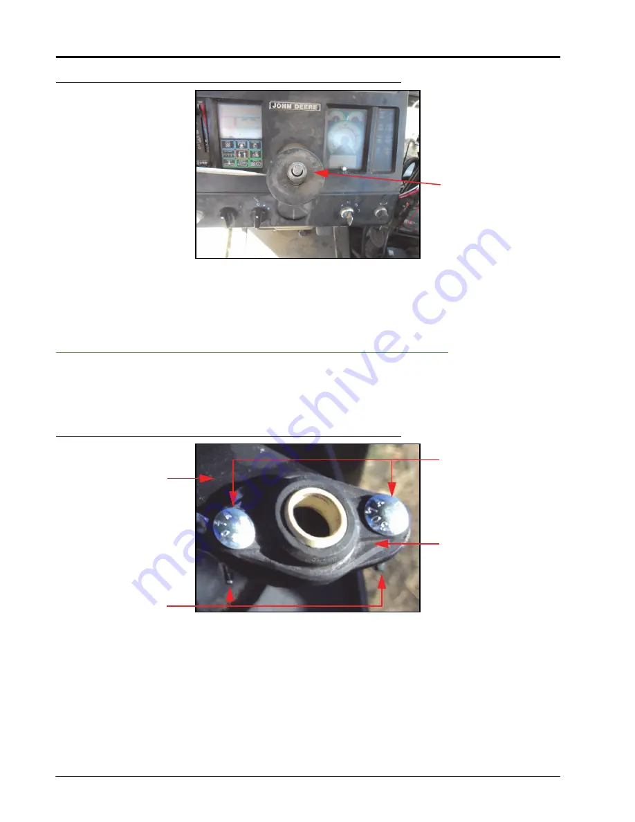
FIGURE 6.
Steering Column Collar to be Removed
7.
Remove the snap ring used to secure the steering column collar.
8.
Remove the collar.
Install the Anti-Rotation Brackets
1.
Identify the anti-rotation bracket mounting location on the lower portion of the steering column that does not
move.
FIGURE 7.
Bearing Installed
2.
Install the 1/2” plastic flanged bearing (P/N 325-0000-036) on the short leg of the collar bracket (P/N 116-
0159-732) using two #10-24 x 3/4” carriage bolts (P/N 311-0069-082) and two #10-24 wing nuts (P/N 312-
3000-013).
Steering Column
Collar
Collar Bracket
(P/N 116-0159-732)
#10-24 x 3/4” UNC
Carriage Bolts
(P/N 311-0069-082)
1/2” Plastic Flanged
Bearing
(P/N 325-0000-036)
#10-24 Wing Nuts
(P/N 312-3000-013)
Summary of Contents for SmarTrax MD
Page 4: ...Table of Contents ii John Deere 8X60 and 8X70 Series SmarTrax MD Installation Manual ...
Page 12: ...Chapter 2 8 John Deere 8X60 and 8X70 Series SmarTrax MD Installation Manual ...
Page 24: ...Chapter 3 20 John Deere 8X60 and 8X70 Series SmarTrax MD Installation Manual ...
Page 30: ...Chapter 4 26 John Deere 8X60 and 8X70 Series SmarTrax MD Installation Manual ...
Page 32: ...Index 28 John Deere 8X60 and 8X70 Series SmarTrax MD Installation Manual ...
Page 33: ......
Page 34: ......


