Chapter 12
212
Viper Pro Installation & Operation Manual
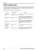
CAN Troubleshooting
Although the control algorithm is located within the CAN node, all of the same troubleshooting techniques used
in a traditional hard-wired system still apply to a CAN system. CAN allows for modularization of the control
system, but the behavior of the system remains the same. Flow and speed sensors, as well as the control
valve and section valves, are used in the same fashion.
Below are some common causes for communication failures:
Issue
Possible Cause
Solution
CANbus cannot
read the product
node
• The node is not
connected to the CANbus
• Connect the node and re-initialize the Viper Pro to read
the product node.
Node is not properly
powered
• Check and reconnect the
power
• Connect the Clean Power - 16 gauge red wire and High
Current Power - 12 gauge red wire from the product
node to a 12VDC power source that is capable of
supplying power to all nodes connected to the CANbus
system
Node is not properly
grounded
• Check and ground the
node
• Connect the Clean Ground - 16 gauge white wire and
the High Current Ground - 12 gauge white wire to a
good, quality ground source. Raven recommends
grounding the wires to the negative terminal of the
battery.
The Boom/Speed
node share power
and ground
connections
• Distribute power and
ground
• Make sure that each node has a separate power and
ground connection.
CANbus ends not
terminated
• Terminate CANbus ends
• Make sure that both ends of the CANbus system are
properly terminated. See Chapter 3,
, for more information.
Summary of Contents for Viper Pro
Page 1: ... Software Version 3 10 Viper Pro Installation Operation Manual ...
Page 42: ...Chapter 3 32 Viper Pro Installation Operation Manual ...
Page 132: ...Chapter 6 122 Viper Pro Installation Operation Manual ...
Page 138: ...Chapter 7 128 Viper Pro Installation Operation Manual ...
Page 180: ...Manual No 016 0171 122 Rev I 170 Advanced Settings and Features ...
Page 194: ...Chapter 9 184 Viper Pro Installation Operation Manual ...
Page 214: ...Chapter 11 204 Viper Pro Installation Operation Manual ...
Page 262: ...Appendix B 252 Viper Pro Installation Operation Manual ...
Page 276: ...Appendix F 266 Viper Pro Installation Operation Manual ...
Page 284: ...Appendix I 274 Viper Pro Installation Operation Manual ...
Page 292: ...Appendix J 282 Viper Pro Installation Operation Manual ...
Page 299: ......

